This has been on my to-do list for way too many years. I got the 568 as part of a lot the better part of 10 years ago. After that, I found a 230, then another. It took another little bit of time to cobble together a pair of working sampling plug-ins, and the special interconnect cable.
Armed with all the pieces, I just couldn’t for the life of me to get the 230 spring to life. With 2 units of cards, the best combination I could get was some cursors moving on one channel, but nothing else.
Starting from the top, I checked the rails first. All was within tolerance. Next we start with the Buffer Card, where all the incoming signals from the scope land. In order for the 230 to start making measurements, it needs the horizontal sweep (the ‘low speed’ sweep), the sweep gate, and the clock pulses (one per sample). It also needs the mV & time settings on the vertical & horizontal plug-ins, and of course, the signal to be measured, but it doesn’t need those to spring into life.
All signals coming into and out of the Buffer Card were as expected. I started poking around at the Clock & Synchronizer Cards, because those generate a whole host of timing signals & gates that actually trigger the measurements. I honestly starting losing my place, because there are a lot of signals that need to be in the right state for the MEASURE signal to fire. I got tied up looking at the !END signal (! meaning compliment, shown with a line over the signal name in this documentation), which was needed to to start, and it started seeming like an infinite loop of sorts.
Oh, and a word on logic levels. This predates TTL logic, and uses active low logic, where a True state is represented by a low level between 0 – 2V, and a False state is represented by a high level between 6 – 12V. The convention in the manual is ‘High’ and ‘Low’, where High is False and Low is True. so for example the MEASURE signal goes Low for a measurement, and the !END signal goes High to indicate the end of a measurement cycle.
To make things even more confusing (and forgive me if I explain this incorrectly), negative logic changes the meaning of NAND and NOR gates, and they’re drawn differently in the schematics. See the NAND gate below. Electrically (shown in the second column), it behaves as a NOR gate, but in negative logic, it behaves as a NAND.

All this to say, there are a few things that make this a difficult machine to troubleshoot. So I cheated. I bought a 3rd, working unit. It arrived exceptionally well packed (so very grateful for that), with a nicely made interconnect cable (I already had a factory one), and it worked as advertised. Finally, I was able to see this beauty in action!
But I said I was going to fix a 230, so I set about starting to swap cards, this time, with a known good unit.
Swapping the Clock & Synchronizer Cards made no change. This supported my suspicion that perhaps they weren’t getting the right signal from the memory circuit. Swapped the memory, no change. The Start / Stop comparators send signals back to the clock, so I tried those next.
It’s always the last thing you try. With the B channel Memory & Zone Generator, I swapped the A Zone Generator with the known good card, and the unit spring to life. Through mechanisms I’m still trying to understand, if you have a bad Zone Generator Card installed with a good memory card, it can lock up the unit into the state I’d been seeing it in. And as luck would have it, I had three bad zone generator cards.
The Zone Generator Card has (2) logic ICs, and 36 transistors, a mix of NPN & PNP, all individually socketed.
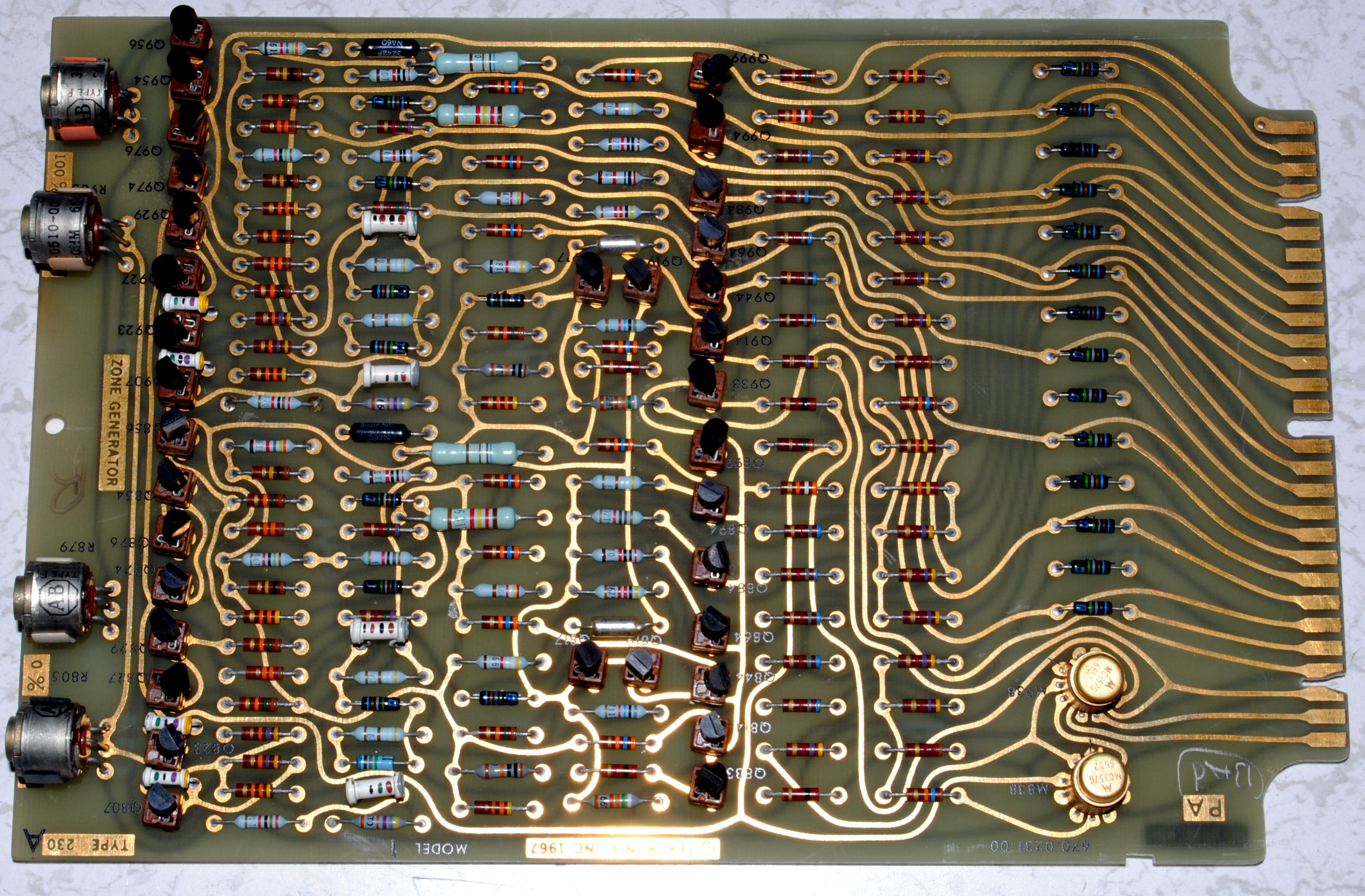
The sockets are a blessing and a curse; It’s easy to swap transistors, but the sockets themselves also become a point of failure.
Sometimes, you want to sit down and dig into a schematic, come up with a hypothesis on why it’s not working, and start probing around to prove or disprove your theory. Other times you just want to brute force a problem, because it’s 11:00 PM, and manual labor is sometimes easier than critical thinking. So I set out to test every transistor in one of the bad cards to see if I could coax it back into the living.

I believe these to be unremarkable transistors, since the application is mostly simple low speed switching. In my model there was a mix of Tek model #s and manufacturer #s:
NPN: 2N3904 / 151-0190
PNP: 2N3906 / 151-0188
I decided to test them on my 575 Curve Tracer at their operating voltage, fearing that perhaps the chinesium battery powered one might miss a fault, since these are operated across 50V rails.
I found 2 culprits:

And with those replaced, the unit sprung to life!

So now we have 2 Zone Generator cards that at least let the unit run measurements, but both have problems. The Zone Generator card generates the areas on the displayed waveform where measurements are made, and show those at highlighted portions on the trace. A zone can be .5cm, 2cm, 4cm or 10cm long (or 12cm, but I’m not getting into that now). When the zone is .5cm, the average of that zone is returned; when it’s longer, the peak is returned.
The first card had an issue where the 0% zone would jump around, and not get to all the locations. We can see in the schematic, there’s a binary coded input coming from the zone position control. Because of the way it was jumping around, I suspected either the 2 or 4 bit, corresponding to Q864 or Q884. Q864 was bad, and replacing it gave me a fully functioning card.

The second card had an issue where the entirety of the 100% zone would be highlighted, so I could only see a movable cursor when only the 0% zone was selected.
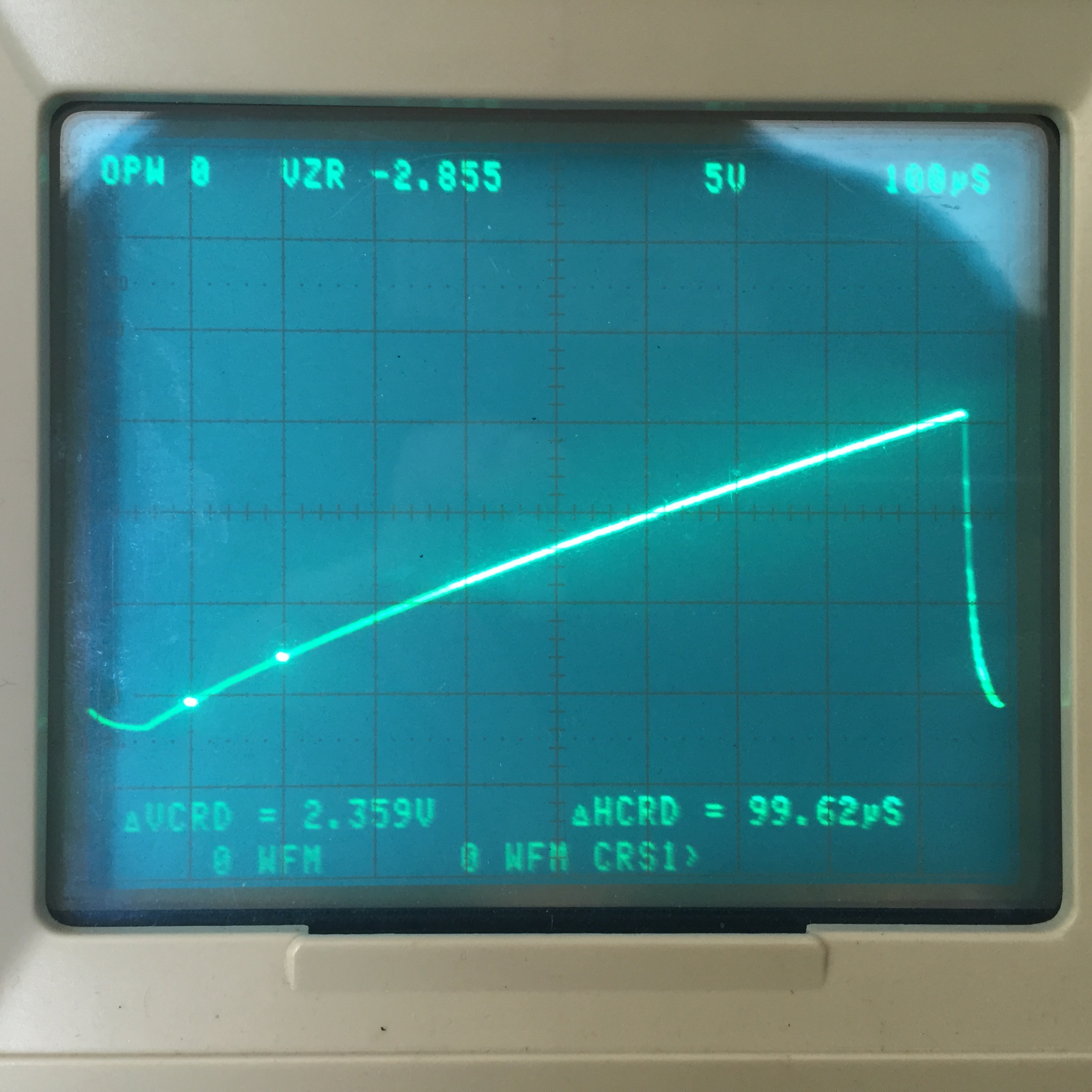
This trace shows 2 good ZONE signals, and the incoming SWEEP GATE on the bottom, which I’m triggering from (thank god for 4 channel scopes). The negative pulses represent the position and width of the two zones.

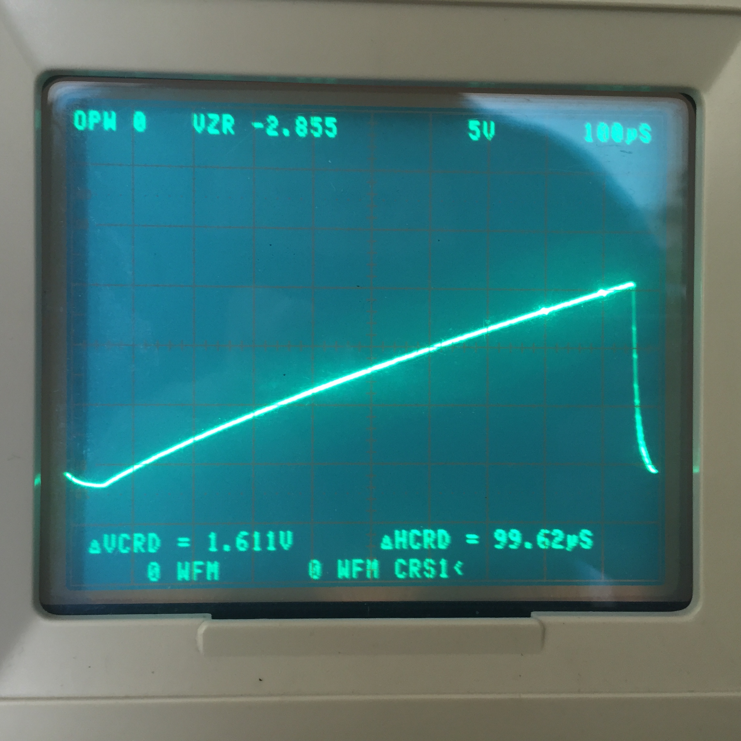
The trace below shows a bad ZONE signal.

I’m seeing this signal coming from M938, but also going into it. Moving upstream, I check Q933. That’s OK. I pull and re-seat M938, and that seems to fix the issue. Now I have a cursor, but it has the same skip issue as the other card. The 100% zone transistors in question are Q964 & Q984. Both of these are good, but re-seating them fixes the issue. Like I said, those sockets are a blessing and a curse.
So now I have 2 more working Zone Generator cards, and a 2nd mostly functioning 230. It’s still wildly out of cal, and there are some quirks with the Nixie display, and cross channel time measurements, but I’ll get to those eventually.