HP 7475A Plotter

Should have started this page a few weesk ago, and taken better notes, but gotta start somewhere.

The Gist: got a plotter; had to replace some rollers; tried with varied success to refill some of the pens; it’s awesome; curves are hard; fonts are harder; workflow needs work.

References (in no particular order):

  • Comment thread w/ chevycasanova & myself on this instagram post.
  • This blog post about truetype fonts, and how some of them are secretly multi-line, even when they claim otherwise. They’re also working in Rhino, so that’s a huge plus.
  • There’s a current, commercial HPGL driver called WinLINE for $190.
  • A blog post about engraving fonts, with some more info about engraving fonts, as well as some links for single-line fonts, also known as open path fonts.
  • Paul Rickards‘ blog

Ah HA! So, the SLF-RHN_Architect is truly an open path font, and here’s how I can tell:
1) using TextObject in Rhino, which lets you type in text but then turns it into polylines instead of editable text, we can see it’s only single lines.
2) using that font in a more traditional application like Word, you can see that it really wants closed outlines to fill. When it doesn’t gets open curves, it does it’s best to fill them in, like this:

And hilarity ensues. Interestingly, this font doesn’t even show up as an option in Inkscape. Odd, since I thought a lot of people used Inkscape to run CNCs and the like, so you’d think it’d have good open path font support. Funny enough, even AutoDesk’s TrueView is exhibiting this behavior when trying to open a DXF with open path trueType fonts.

So I appear to have 2 truly open path fonts, SLD-RHN Architect, and MechSoft_Font-1. Unfortunately both of them have smooth curves, which poses a problem for my plotter. Because the plotter ends up treating curves as a series of small lines, there’s a tiny pause between each change in direction, and that makes for a slower path that leaves a lot more ink on the page.

The two fonts that would appear to work well on the plotter are Simplex & Txt. Both of which are available in AutoCAD as .shx files, but both of who’s .ttf equivalents are not open path.

Simplex font
Txt font

Right now my workflow originates in Rhino3D. I’ve had access to Rhino for at least the past 10 years through various jobs, and if I ever really need to, I’ll just buy a copy for myself. It’s a thousand bucks for a perpetual license, and it’s fantastic software I’d feel good about plunking down my own hard-earned cash for.
Coming out of Rhino DXF, I’ve got a few options to get it to the plotter.

  • AutoCAD: In AutoCAD, I can swap out font styles for plotter-friendly SHX fonts, plus the plotter driver is great. The problem is I’m not sure I’ll always have access to AutoCAD, and it’s expensive AF.
  • AutoDesk TrueView: This can just open DXFs and send them to the plotter, but I can’t make any font changes. I’m not 100% sure about it’s support for TrueType open path fonts. That’s on the list of things to check. If it doesn’t support them, I’d have to lay down text in Rhino using the textObject command, which makes polylines from fonts. The downside there is the text is not editable.
  • Inkscape: Inkscape has rudimentary HPGL support, and from what I saw, it was ‘good enough’ (maybe). It did not handle open-path fonts out of the box, but someone mentioned there’s a extension to convert fonts to open paths. Its… not going great.. more below.

Adventures in Inkscape

For whatever reason, regardless of regular text or the ‘Hershey’ text (which gets converted to SVG paths), the plotter loses it’s mind after a few characters.
I was also having a problem even getting simple shapes to show up on the right position on the page, but de-selecting ‘auto-align’ in the Plot features page seemed to fix that. Making a simple rectangle on the page seems to yield generally good results in terms of scaling.
I’m also disabling ‘overcut’, ‘offset correction’, and ‘Precut’.

Yeah, I’m getting nowhere with Inkscape. It shits the bed after the first few characters. Maybe I’ll try slowing down the baudrate, but it’s weird that there wasn’t the same problem from AutoCAD.

SOLVED: It was flow control. For whatever reason, in AutoCAD / TrueView, I had to set software flow control (Xon/Xoff), but in Inkscape, I had to enable full hardware flow control (DSR/DTR & RTS/CTS). Thanks Paul Rickards for the tip!

Next thing to work out in Inkscape is curves – they’re printing quite slow, and it looks like it’s because they’re coming in as a series of polylines

See all those little points? that’s the problem

This happened because I exported it as Polylines. I tried “Natural” export next but for some reason that ended up obliterating all of the resistor zig-zags ?!?!

Dude, where’s my resistors?

A Working Recipe, Take 1:

OK, getting closer:

  1. Save as DXF from Rhino using the ‘default’ profile (not polyines, not natural, just default. Don’t over-think things, Paul)
  2. Open in Inkscape, make ‘FifteenTwenty‘ the default font
  3. Re-align all the text & resize fonts as needed. Dunno why, but it comes in shifted, and not in a predictable way, like you can’t just grab them all and nudge a little.
  4. Select all text and change the font to ‘FifteenTwenty UltraLight’. At this point the stroke becomes invisible.
  5. With all text still selected, hit Shift-Control-C to turn the text to paths.
  6. Give the still selected objects a solid stroke so you can see them again for any last checks.
  7. Plot it!

Alternatively, I can just use Fifteen Twenty in the TextObject command in Rhino and do all my text aligning there. Maybe that’s the move.

So I found out that the FifteenTwenty font isn’t actually an open path font; it’s has closed loops that trace back over themselves. Keeping it as a font in Inkscape vs converting it to paths makes no difference. Making it paths using the TextObject tool in Rhino should work, but some shapes just don’t import correctly into Inkscape:

Rhino on top, resulting import in Inkscape on the bottom. DXF looks fine in AutoDesk viewer.

And just to prove I’m not crazy, here’s DXF linework from that font-in-progress I was working on opened in a TrueView on top, and Inkscape on the bottom. So Inkscape is just ignoring some polylines ?!

Fortunately, rhino can export SVG, so I think we’ll just go that route.


Trying to make my own font:

I tried to take the Txt font and make it single path. With a lot of manual work, I was able to make a set of numbers and uppercase letters to play around with. They work well with Rhino’s TextObject command, but they do not work well with the regular text command.

There’s something special about SLD-RHN Architect, and MechSoft_Font-1 that makes Rhino render them correctly.

Stewart Russell’s Fifteen Twenty font has a single stroke style which also doesn’t display in Rhino.

AT Computer ephemera

I scored a 486 in a full size AT case for $50 at VCF 2024, and it inspired me to go through all my AT x86 gear in the hopes of building up a system. I found the following motherboards in my collection

486 DX 33

This is the motherboard that came with the case. Not winning any speed races for sure. It seems to work OK. There’s some corrosion where the CMOS battery was (which was removed), and I’ve got some CR3032 battery holders on the way to solder in place. Not sure what it’s ultimate fate will be.

486 DX4 100

A PC Chips M912

This I got at a VCF swap-meet last year. It’s a VLB motherboard, and I got a VLB video card & IDE card to go with it. Unfortunately, it appears to be dead. I picked up a POST card and it just shows dashes on the display, and nothing else. Not sure if it’s a dead CPU or bad mobo; I also tried the DX33, but that was before I got the POST card. More investigation required.

Socket 7 w/ Pentium 120

First of all, I completely forgot I had this; I have no idea where it came from, but I found it in one of my retrocomputing boxes. Thanks to The Retro Web’s awesome website, I was able to determine this is a PC Chips M530. Mine says ‘V1.6A’, while the one on the site is ‘V1.6B’. The only visible difference being the presence of a CMOS battery holder, which mine lacks.

And this lack of a CMOS battery holder is proving to be a bit of a pickle. I spent a while going over the documentation and can’t see anywhere this would wire up to. There are a few pins lifted on the realtime clock, a VIA VT82885. It’s a standard DIP, and doesn’t have a battery in it. After looking at a close-up shot I took, I finally noticed a ‘+ ‘ and ‘- ‘ marked above two of the pins.

The pin marked negative is called out as not connected in the data-sheet, but sure enough, giving it 3.3V across these two terminals clears the CMOS battery error and seems to hold the BIOS info. Right now I’ve got it precariously connected to a bench supply; once the battery holders show up, I’ll probably just solder one across these pins. I would like to know what the original arrangement was though. The pins are not only bent out of the way, but are also broken, so I couldn’t reinstate the original config without getting a replacement chip (which a cursory search on eBay didn’t turn up).

There’s a jumper, J7 that’s called ‘External Battery Selector’, and it’s to be left open by default. If closed, I’m just not sure where the external batter would be attached. I suppose I could go probing around to see if any of the jumpers or unlabeled pads land at the Vbat pin on the RTC socket, but without a replacement chip, it’s a moot point.
Is the venerable Dallas RTC chip a drop-in replacement? The pinout of a DS1287 looks similar. I wonder if that’s what used to be in here what I’m seeing is a hack to work around a Dallas chip that had gone bad. For now I think the best course of action (and certainly the least expensive) is to bodge a battery back on to those two pins.

I was able to install DOS 6.22 onto a CF card using a CF to IDE adapter. The card was 8GB, which is recognized by the BIOS, but in DOS it only shows up as 2GB (I seem to remember this… ) and I believe it’s a FAT16 format. So a few questions:
1) How can I multi-boot and have access to the whole 8GB
2) Related, in the BIOS, there are 3 different ways I can set this drive:

  1. Normal – 15525 Cylinders & 16 Heads
  2. Large – 7762 Cylinders & 32 Heads
  3. LBA – 974 Cylinders & 255 Heads

All those options have 16 Sectors. Auto defaults to the same settings as Normal. ‘LBA’ Stands for ‘Large Block Addressing’, but that’s all I remember.

Back to the RTC battery – I got new battery holders, but managed to snap one of the pins trying to solder to it. I even managed to expose some copper with a grinder, but ended up breaking that too. So yeah.. Gonna have to get a new replacement.
According to this Vogons entry from someone who appears to have the same board, the Dallas DS12887A RTC is compatible enough with the VIA82887 / HT12888A. For $6, I can get a replacement from China. For $25, I can get a drop-in replacement board that has a replaceable battery.
This machine is turning into a money pit.

BIOS Update:

I was able to file away a little more of the chip to expose just enough copper to solder to. The key is gluing these copper pads on top of the chip so you can attach to the pins via fine wire and keep any strain from transferring to them from the larger wires.

It “works”!

Jumping around a bit here – here’s what I think the pinout is for the clock display. A collection of pinouts can be found here

https://www.minuszerodegrees.net/led_speed_display/LED%20display%20-%20K-568.jpg

Networking:

Thanks to this page, I was able to get the network card working with little fuss

Floppy Drives:

I got a gotek as drive A: & the original 3 1/2″ drive as B:, but I’d like get the 5-1/4″ drive working as well. I found this multi-function card in one of my retrocomputing boxes, and I’d like to enable only the floppy port at first. I’ve found two references to similar cards that use this chip, but not the exact one.

One page suggests this pinout, except I’ve only got 9 pins instead of 11.

This entry in Stason.org lists 12 jumpers, but in both cases, the floppy enable is the first one, so I’m going to assume that’s a pretty safe bet.

No idea whatsoever if this is going to interfere with the built-in controller.

Weeeeell this might be a dead-end. Even with all the jumpers in the disabled position, the machine hangs at the enter setup prompt.

Networking & Soundcard conflicts:

Both the network & soundcard wanted to be at IO 0x220. I could change the IRQ in the SBLASTER line in Autoexec.bat, but changing the IO would shoot an error. Using the network card’s utility, I was able to set it from PnP to Jumperless, and set the IO to 0x240.
With that resolved, I can get the machine to boot with both cards installed, and they both appear to work. They do, however, both share IRQ 5 at the moment. Not sure if that’s going to be a problem. I should also think about a battery hack for the NVRAM on the network card.

SCSI:

I had an Adaptec 2940U kicking around – after a bunch of trial and error, what ultimately worked was calling ASPI8DOS.SYS in Config.sys (following the driver instructions were fine, except for which of the ASPIxxxx files to use).

Sencore LC102

My downstairs neighbor Ben loaned me his Sencore LC102 so I could start troubleshooting my newly acquired Tektronix 576 Curve Tracer that I suspected had some bad caps (spoiler alert, it had many bad caps). I’ve typically slummed it with my Heathkit IT-28 to check PS caps, but that’s not really as useful for lower voltage caps, nor will it tell you anything about ESR.
I’ve tended to ignore Sencore equipment on the count of it’s membrane buttons and non-backlit LCD displays, but damn this LC102 is useful. Ben just so happened to have both a working and non-working unit, and let me hang on to both for a bit.

The bad unit will fire up, but won’t test a cap. It will also lock up if you hit the ‘lead zero open’ switch. The other telltale symptom that something is amiss is a distinctive whine coming from the unit’s power supply, specifically this transformer:

We thought at first the noise was coming from the SMPS responsible for generating the test voltages, but this one handles the +/- 5V rails. The rails measure OK, but this circuit is clearly working overtime to make that happen:

For reference, here’s the good unit:

Here’s the output of the PWM driver on the bad unit:

And here’s the PWM output on the good unit:

Note the frequency readout on my 7854 is being generated by my new-to-me 7D15 plug-in, sitting in the ‘B’ horizontal slot, getting the signal from the trigger pick-off. I know any basic scope can do that these days, but that was cutting edge back in the early 80s.

Also note that the Circuit description says this frequency should be around 27KHz, but this is closer to 16KHz.

So there’s one of two things going on:

  1. Something in the rest of the circuit that uses the +/-5V rails is taxing the power supply, causing it to work harder to maintain these voltages.
  2. Something is awry in the power supply circuit itself.

Given how hot the circuit gets, I don’t want to run the bad unit for too long. I think the best place to start is to measure DC resistances from ground to the voltage inputs on the main board.

Another thing I learned while making these measurements:

  1. tables in wordpress is wet, hot garbage (at least WPTableBuilder is)
  2. The chassis is 100k away from ground (?!) there’s actually 3 different grounds – chassis, circuit & input.

Rail

pin

good unit

bad unit

+5V

P4 - 5

1.37k

1.16k

-5V

P4 - 4

9k

1.33k

+12V

P4 - 6

1.38k

1.54k

+18V

P4 - 7

540k

870k

So right away, that discrepancy on the -5V rail is a big red flag. Lets investigate. Where does the -5V rail show up? A lot of places:

  • It’s on the supply of every opamp
  • It’s a part of the offset null circuit on some opamps (a feature I’m not familiar with)
  • It feeds a pair of 4051 multiplexers
  • It feeds a MC14433 A/D converter
  • It feeds something called the “Ringer” circuit.

Here are all those locations in the schematic (click to get the PDF):

I’m going to rule out that ringer circuit for now since the first thing that the -5V rail hits is a 10k resistor, and I’d be real surprised if that was shorted.

Actually, scratch that – the next thing to do is look at the main board with a thermal camera.

Here’s the good one

and here’s the bad one

A clue! What’s getting really hot is IC27, an LM319 in the capacitance measuring portion. IC22, a TL084 opamp that’s a part of the current source circuit is also getting warmer than expected. The other half of that dual opamp is in the ESR measuring circuit.

I measured the output of IC22 into the LM317, and it’s -1.8V. On the bad unit, it was +3.3V. And here’s where I’m going to say a bunch of things that are probably wrong: With -1.8V on the regulator, it’s essentially shut off – I would expect this since it’s a higher range; and you wouldn’t have a higher range enabled during power up.
Something is causing the regulator to be on in the bad unit. Is it an erroneous signal from the microcontroller, a faulty opamp, something with it’s surrounding analog circuitry, or a problem with the LM317?
I expect pin 12, the input from the microcontroller, to be low. It is on the good unit, but on the bad unit, it’s at like 1V, which is odd, and wrong. I wonder if the next move is to yank the LM317.

Ok, yanked the LM317. With that out of the picture, The SMPS is no longer angry; it’s not buzzing, nor is it getting super hot. The LM319, however, is still getting getting very, hot, theres now +2V coming out of IC22 pin 14, and .4V on the input terminal pin 12. I can’t make that make sense to me.

I mean, fuck-it do I socket IC22 & IC27 next? I feel like they may not be the problems and are just collateral damage, but I’m not sure what to do next.

— The Next Day —

IC22 & IC27 have been socketed. With both removed, and the LM317 reinstalled, the power supply doesn’t whine anymore. With IC22, the TL084 quad opamp reinstalled, the whine returns. I threw in a TL074, and the whine stopped. I measured the resistance between the positive & negative terminals on both devices; on the TL084 I pulled out of the unit, I measured 340 ohms. On the new TL074, I measured 3 Meg, which is closer to what I’d expect. Reinstalling the LM319 Comparator made the whine come back. Measuring between the rails on that chip yields a similarly low value. I’m waiting on replacements. Fingers crossed this is it.

— Parts are in —

I replaced IC27, the LM319 Dual Comparator with a new part I got off eBay. Thermal camera looks good, but I’m still getting the same issue:

  • Open Test, with input open: I get one progress dash on the screen and the unit hangs.
  • Open Test, with input shorted: same thing.
  • Short Test, with input shorted: Error 4
  • Short Test, with input open: Test runs and says ‘Open’ (is this correct?)

Note that the chip labeling looked a little suspect at first, so I whipped up breadboard set-up just to check it out. The Power Designs triple output supply is new to me, and I’m a fan.

Testing some suspicious looking chips from eBay

Something is still fishy in this neighborhood though –

Here’s a few measurements from the good unit.

Pin 10, the input of the Comparator IC27
Pin 9 input of the comparator IC27 – the high limit

I’m going to post a few more pics of signals on that comparator, but I think it might be a red herring. The input signals on pin 5 of IC27 are driven by a pair of MOSFETS, which in turn are driven by two pins on the main processor. Those signals are different on the good unit vs the bad unit, so either there’s EPROM bit-rot (possible but unlikely) or much more plausible, the CPU isn’t getting the right signal from somewhere else to set those pins correctly.

Looking for a new lead, I’m turning again to the thermal camera.

Here’s the bad unit, on for about 45 minutes. IC23, another dual op-amp, looks unusually hot.

The bad one

Here’s the good one, on for maybe 25 minutes (yes yes, I know, it’s not the same amount of time, bla bla bla…). IC23 is warm but a good 20 degrees F cooler. The hottest of the lot though is IC3, the regulator that’s responsible for the 12V reference.

The good one

There’s already a 12V line from the power supply, so we’ll need to do some sleuthing in the schematic to see where this reference line goes. The fact that it’s dead cold in the bad unit could be another clue. I may also desolder IC23, though I think I’m fresh out of quad op-amps at the moment.

I checked resistance between the positive & negative supply inputs of that opamp in circuit (oddly +12 & -5) on both good & bad units, and they both read 3.3k, so I’m no longer suspecting a shorted IC.

Well, things are getting weirder. I double-checked the rails on both the good one and the bad one – they’re all as expected (but note that +12V means more like +13.8V). The 12V reference on the bad unit is bang on at 12.00V. The 12V reference on the good unit is only like 11.7V, so I wonder if even the good unit is harboring some gremlins. Also, another dead lead.

I’m not admitting outright defeat, but I’m going to retreat to other endeavors for now.

7/20 Update: Defeat has been admitted. A friend found me a Sencore LC53 for cheap, and so I bailed on this and gave it back to Ben.

Everex 386is

Aaaand, I let another year go by without posting. I suck.
Next on the bench – an old 386 computer. I’ve been in the mood to poke at one of these for a bit; last time I had one was squarely in the 90’s and I was running linux on it (probably slackware, maybe redhat).

It boots successfully into BIOS, and has a great front panel character display. I’m going to disassemble it to get part #s off all the components.

Motherboard: EV-1806 Rev G
Turns out this is a 286 motherboard, and what makes this a 386 is the Everex InSTEP daughtercard.

The daughtercard plugs into the the 80286 & 80287 sockets. It has a 80386SX-16 soldered on, and a PLCC socket for an 80387 (which is annoying, since most I’m finding on eBay are PGA).

There is a 5 1/4″ and 3 1/2″ drive, a Teac FD-55GFR and FD-235HF respectively. A cursory search seems to indicate that the 3 1/2″ drive is High Density, so I’m going to make a plain old 1.44Mb DOS bootdisk.

The Drive Controller is An Everex EV-346M. It supports (2) floppy drives from 360kB to 1.44MB, and 2 MFM hard drives. It says only ST506/ST412, but I’m wondering if that’s really the case. I’ve got a pair of ST 225 drives that I might want to try out. Worst case, I’ve got a few other controllers. I was surprised to find an MFM controller; I thought IDE drives were commonplace by the mid 90s.

The Video Card is an Everex E3EEV-628. Not really sure there’s anything to say about it?

I made a DOS 6.22 boot disk, but the way it’s set up, the 5 1/4″ was the A drive. Just flipping the cables so the 3 1/2″ didn’t work -the disk light came on, but still got the classic ‘non system disk or disk error’.

So lets look into the dip switch settings on the 3 1/2″ Ah – there’s a DS0 & DS1, and DS1 was jumpered, so lets switch to DS0. No apparent change. I really need to brush up on floppy drive wiring, but I’m going to beat on this blind for a bit more. I don’t actually know if this drive is any good, or if I’ve even made a bootable disk.
Yeah, so I’m an idiot – I tried just copying the files over onto a floppy disk (I’m on a mac), but in doing so, you have no way of stipulating what ends up where; the BIOS starts executing from sector 0.
It was able to make a bootable disk in a Win10 VM, and it got me to an A: prompt, but a DIR failed. I’m not entirely surprised. It turns out making an old school DOS boot disk is a pain in the ass in 2022. I found bootable images at Winworldpc, and am using a trial of WinImage to write the image to a floppy. I was able to boot into the DOS 5.0 setup disk, but it wanted me to set up to a hard-drive. I also couldn’t exit out of setup and resume it, or even run a DIR command. I need to find a good bootable, single floppy OS.

There’s something funky going on – I grabbed a 6.22 boot image from here, but I’m still not able to get a proper boot – it tries to load a CD rom drive and fails, and after that it tells me it can’t load COMMAND.COM.

I also tried an earlier version that looks like it’s a single 720k disk. I was able to write it using DD directly in MacOS. Mac even recognizes it as a 720k disk, and sees it’s contents, but it won’t boot.

Fuckit, let’s try linux? Trying Fdlinux.
I’m not super crazy about seeing
dd: /dev/disk3: end of device
2881+0 records in
2880+1 records out
Seems the latest version expects you to do some tricks to format a slightly larger drive, but the previous version seems to fit on a standard disk.
I finally at least got a meaningful error from LILO (remember LILO?!):
Error 0x80. this is a disk timeout, suggesting an issue with either the drive or the media. So it’s time to try either another drive, or a damn gotek, I guess.
I appreciate floppies from a nostalgic perspective, but I’m remembering just how much they suuuucked.

3/3 Update:

Yeah, the floppy drive was bad. Goteks (with flash floppy) are great for permanent install, but I’ve got a Lothartek HxC SD that’s great for troubleshooting. I got this with an Atari ST a few years back, and it’s an old model; the only thing to watch out for is that the SD card has to be formatted FAT16. This is easily accomplished on Mac OS with:
sudo newfs_msdos -F 16 /dev/disk3

I was able to boot into DOS, and hooked up a Seagate ST-225 20MB MFM drive. Fdisk was unable to add a partition, however a low level format using Speedstor seemed to do the trick. It’s a great utility, and honestly I need to refresh my memory on what a low level format is.

4/2 Update:

Hard Drive
I was excited to find that I’ve got a working MFM drive, but decided to save it for a machine that might really need it. I had in my stash, a no-name IDE & Floppy drive controller, so I decided to see if I could get that to work with a CF card. Because the BIOS is so decrepit, I wasn’t able to get it to work. Enter XTIDE – an alternative BIOS that supports more modern drives. I was able to burn the 8k AT version onto an EPROM, and install it into a no-frills network card. Through a combination of dumb luck and wizardry, it actually freakin’ worked: After the built-in BIOS runs, XTIDE runs and lets the machine see the CF card. DOS was able to format it and install on to it. And since it’s just a FAT16 formatted volume, I can yank the CF card and put it in a reader to do bulk copies of software.

Floppy
I replaced the bad 3 1/2″ drive with a Gotek running FlashFloppy. There’s a bunch of different flavors of “goteks” out there, and they have different methods of flashing the software. For this one, I needed an USB A to A cable, and had to run some utility in Windows. Works fine now.

Math Coprocessor
I installed a 387 Math Coprocessor. Linux now gets a little further into booting, but still hung. I’ll play around with this some more some day.

BIOS Battery
I got tired of having to go through setup every time, so I cobbled together a CR3032 battery mount for it.

Next Steps:

Network Card
Can I find drivers for it? It’s a Racal InterLan, and thanks to this page, I was able to figure out how to use an EPROM with it. It claims it to be an NI5210 card, and I found what looks to be drivers that match on Archive.org, but I haven’t figured out how to install them.

Soundcard
A soundblaster AWE64 Value is what I’ve got – it’s not the best card for this setup, but it works OK. Installation went fine, you just need to install the S64Basic Driver, and make sure that you’ve already expanded the CTCMBSS folder, which contains the plug-n-play drivers that the installer will ask for.


Akai S900

Taking a quick detour from oscilloscope repair to attempt to fix a RAM error on an Akai S900 sampler that I just scored for cheap. The two issues were a dim backlight, and RAM error “Bad RAM Bit DK09”

the logic board – check out that honkin linear power supply

Thanks to DOSputin for compiling a reference of what codes refer to what chips here.
The best copy of the service manual can be found at this page, along with a wealth of other info on the S900.

DK09 refers to IC62. This thread confirms that there’s no way to test them all at once; you only get one bad ram message at a time, which means you have to take the whole damn thing apart, change the ram, reassemble it, then do the test again to find out where the next problem is.

Someone has been in this unit before. 3 of the 6 screws to attach the voice board were missing. It appears someone had dealt with a RAM issue before, as IC60 is now socketed. I’d planned on doing the same. After replacing IC62, I get another error: DJ12 – IC57. Fortunately, that was it, now the RAM test passes.

The latest firmware is V1.2C. I have V1.2A. I don’t think this matters, as I boot to what’s either called OS2 or OS4 with a floppy.

First attempt with the EP-1 programmer

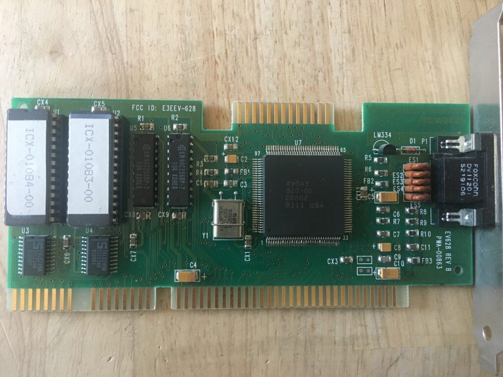
Finally got this thing working.
Funny story – I actually had one of these in storage, but it was cheaper just to buy a new one than to rent a zip-car and make a special trip just for this one piece.  So now I have two BP Microsystems EP-1 programmers…

Here’s the Manual
UPDATE: Thanks to John Spina on the Vintage Test Equipment group for pointing me to the original software and firmware updates.

UPDATE:  Thanks to Rodger Whitaker for pointing out this modern USB programmer from Batronix that supports older chips. ~200 euro.  Not cheap, but not as expensive as I expected.

I was able to use Serial.app in OSX to connect to my old Radio Shack USB-serial adapter, which I couldn’t get to work on my Win10 box.  The programmer doesn’t need any additional software, it serves up it’s interface over the serial port.  It automatically detects the baud rate, up to 38,400.
To read a chip:

  1. ‘C’ brings up a menu to select the chip by make then model
  2. ‘PROTO’ lets you select the protocol – I had success using XMODEM.
  3. ‘RH’ reads a hex file – it will send the file once you initiate an XMODEM receive via the terminal emulator

Some other useful commands:

  • STAT – lists the current baud rate, firmware, selected chip type, and protocol.  It also has the phone number for BP Microsystems, which is still in business, and still has the same number (contrats guys!)
  • LIST – shows the contents of the chip, with a familiar hex viewer layout
  • BLANK – confirms that the ship is blank (all FFs)

There are also a number of commands for reading files in different formats (Intel, hex, Motorola, and Tektronix (?)), manually programming segments of a chip


Programming a chip:
This is where I’m getting stuck.  I’ve already incorrectly programmed one chip with a single character.  I have to find the correct combination of protocol and upload settings.
OK, I’ve got a bunch of EPROMs I can try programming once before my eraser shows up.

Attempt 1:
Set programmer for XMODEM,
Set transfer for XMODEM, no 1K block size
Appears to work correctly, but then I get the following:
Bytes received; 6 hex file errors;
1 bytes programmed correctly, no errors.
Only the first byte is programmed, and not even the correct one.

Attempt 2:
Same as above, but convert to HEX file first.
Appears to be working correctly, and takes a lot longer.
Appears to work correctly, reports:
00 Bytes received;
2000 bytes programmed correctly; No errors.
2000h = 8kB, so that’s promising.

I used this site to make the bin to hex conversion (would love to find an offline solution) What worked for me was no delimiters, but newlines every 16 bytes.

When we read it back and diff with the original, we get a file that’s 1kB larger, and seems to have carriage returns (0x0D) every 32 characters.  I can’t tell if this is a readback error, or a programming error.
It’s a read-back error.  Using ‘RB’ gets the file back in straight binary, and comparing it to the original file from the wiki I used to burn it from shows no errors.
SUCCESS!

SO: Even though the programmer can send us back binary files, we have to send it hex files.  Lesson learned!

Supported Chips

If anyone is interested, here’s a complete list that the programmer spits out with the ‘PARTS’ command:

AMD
8753H *1B,C 8751H *1B,C 87C51 *1C Am27128
Am27128A Am2716 Am27256 Am2732
Am2732A Am2732B Am27512 Am2764
Am2764A Am27C128D Am27C128P Am27C256
Am27C512 Am27C64D Am27C64P Am2817A
Am2864A Am2864AE Am2864B Am2864BE
Am28C256 Am9716 Am9761H *1B,C Am9864

Atmel
AT27C128 AT27C256 AT27C256R AT27C512
AT27C512R AT27C513 AT27C515 AT27HC256
AT27HC256L AT27HC64 AT27HC641 AT27HC64L
AT28C04 AT28C04E AT28C04F AT28C16
AT28C16E AT28C16F AT28C17 AT28C17E
AT28C17F AT28C256 AT28C256E AT28C256F
AT28C256E AT28C64 AT28C64E AT28C64F
AT28C64X AT28HC16 AT28HC16L AT28HC16L
AT28HC191 AT28HC191L AT28HC256 AT28HC256E
AT28HC256F AT28HC256L AT28HC256LE AT28HC291
AT28HC291L AT28HC64 AT28HC64E AT28HC64L
AT28HC64LE AT28PC64 AT28PC64E

Bowmar/White
8014 8020 8023

Catalyst
CAT27128A CAT27256 CAT27512 CAT2764A
CAT27HC256 CAT28C16A CAT28C17A CAT28C256
CAT28C64A CAT28C65A

Dallas Semiconductor
Dense-Pac
DPV27C256 DPV27C512

Electronic Arrays
EA2716

EXEL
XLS2804A XLS2816A XLS2817A XLS2864A
XLS2865A XLM46C15 XLM46C16 XLM46P15
XLM46P16 XLS46C15 XLS46C16 XLS46P15
XLS46P16

Fujitsu
MBL8742H *1A MBL8749H *1A MBL8749N *1A MBM27128
MBM27128-X MBM2716 MBM2716H MBM27256
MBM27256-W MBM27256-X MBM2732 MBM2732A
MBM2764 MBM27C128 MBM27C128P MBM27C256
MBM27C256A MBM27C256A-W MBM27C256AP MBM27C256H
MBM27C512 MBM27C512P MBM27C64 MBM27C64-W
MBM27C64-X MBM28C64 MBM28C65 MBM83256
MBM83512

Generic
27011 (12.5V) 27128 (21V) 27128A (12.5V) 2716 (25V)
27256 (12.5V) 2732 (25V) 2732A (21V) 2732B (12.5V)
27512 (12.5V) 2764 (21V) 2764A (12.5V) 27C128 (21V)
27C16 (25V) 27C256 (12.5V) 27C32 (25V) 27C512 (12.5V)
27C64 (21V)

General Instrument
27256 27C128 27C256 27C512
27C513 27C64 27HC64 27HC64L
28C04 28C16 28C17 28C64
28CP256 28CP256A 28CP256B

Greenwich
GR27128 GR27256 GR27512 GR27513
GR2764 GR281 GR881 GR3281

Hitachi
HN27128A HN27128AG HN27128AP HN27256
HN27256G HN27256P HN27512 HN27512G
HN27512P HN27C256 HN27C256FP HN27C256G
HN27C256HG HN27C64 HN462532 HN462716
HN462732 HN4827128 HN482732A HN482764
HN58064 HN58C65 HN58C66P

Hyundai
HY2764 HY27C64

IDT
IDT78C16A IDT78C256A IDT78C64A IDT78M64
IDT78M64S

Intel
27011 27128 27128A 27128B
2716 27256 2732 2732A
27512 27513 2758 2764
2764A 27C128 27C256 27C512
27C64 2816A 2817A 2864
2864A 68C257 8041A *1A 8042 *1A
8048AH *1A 8049AH *1A 8050AH *1A 8741A *1A
8741AH *1A 8742 *1A 8742AH *1A 8744H *1B,C
8748 *1A 8748H *1A 8749H *1A 8751H *1B,C
8755A *1A 87C256 87C257 87C51 *1C
87C64 P27128A P27128B P27256
P27512 P27513 P2764A P27C128
P27C256 P27C64

Microchip Technology
27256 27C128 27C256 27C512
27C513 27C64 27HC256 27HC256L
27HC64 28C04 28C04F 28C16
28C17 28C64 28C64A 28C64AF
28C64AX 28C256 28CP256

Macronix
MX27C256 MX27C64

Mitsubishi
M5L27128K M5L27128K-I M5L27256K M5L27256K-I
M5L2732 M5L27512K M5L2764K M5M27128P
M5M27256P M5M27512P M5M2764P M5M27C128K
M5M27C256K M5M27C256AK M5M27C256P M5M27C512AK
M5M27C512AP M5M28C64AP M5M28C64P

Mostek
ET2716 ETC2716 ETC2732 MK2716
MK2764 MK38XXX

Motorola
MCM2532 MCM2716 MCM68764 MCM68766

National
MM2716 MM2716E MM2758-A MM2758-B
NMC2732 NMC27C128B NMC27C128BQ NMC27C128BN
NMC27C128C NMC27C128CQ NMC27C16 NMC27C16H
NMC27C16HQ NMC27C16Q NMC27C256 NMC27C256Q
NMC27C256B NMC27C256BN NMC27C256BQ NMC27C32
NMC27C32B NMC27C32BQ NMC27C32E NMC27C32EH
NMC27C32H NMC27C512 NMC27C512A NMC27C512AN
NMC27C512AQ NMC27C64 NMC27C64N NMC27C64Q
NMC27C64B NMC27C64BN NMC27C64BQ NMC27CP128
NMC27CP128Q NMC9817 NMC98C64A

NEC
8748HD *1A uPD27128 uPD2716 uPD27256
uPD2732 uPD2732A uPD2764 uPD27C256
uPD27C256A uPD27C512 uPD27C64 uPD28C04
uPD28C05 uPD28C64

OKI
MSM27128A MSM27128AS MSM27128AZB-RS MSM2716
MSM27256 MSM27256AS MSM27256ZB-RS MSM2732
MSM2732A MSM27512 MSM27512AS MSM27512ZB-RS
MSM2764 MSM2764A MSM2764AS MSM2764AZB-RS
MSM2764RS MSM27C128AS MSM27C64AS MSM2816ARS

Quick Pulse
27011 27128A 27256 27512
2764A

Ricoh
RD27C256 RD27C64

Rockwell
R2764 R2764C R27C64 R2816
R5213 R52B13 R52B33 R87C32
R87C64

Samsung
KM2816A KM2816AI KM2817A KM2817AI
KM2864A KM2864AH KM2865A KM2865AH
KM28C64A KM28C65

Seeq
27128 27256 2764 27C256
2804A 2816A 2816AH 2817A
2817AH 2864 2864H 28C256
28C64 28C64A 28C65 36C16
36C32 38C16 38C32 5133
5213 52B13 52B13H 52B33
52B33H 5516A 5516AH 5517A
5517AH 55B33 55B33H 82005
82025 86063 E52B33 E52B33H
M52B33 M52B33H

SGS
ET2716 ETC2716 ETC2732 M27128A
M2716 M2716P M27256 M27C256B
M27C512 M2732A M27512 M2764
M2764A ST27128A ST27256 ST2764A
ST27C256 TS27C256 TS27C256P TS27C256Q
TS27C64 TS27C64A TS27C64P TS27C64Q
TS28C16AC TS28C16AP TS28C64C TS28C64P

SGS/THOMSON
ET2716 ETC2716 ETC2732 M27128A
M2716 M2716P M27256 M27C256B
M27C512 M2732A M27512 M2764
M2764A ST27128A ST27256 ST2764A
ST27C256 TS27C256 TS27C256P TS27C256Q
TS27C64 TS27C64A TS27C64P TS27C64Q
TS28C16AC TS28C16AP TS28C64C TS28C64P

Signetics
27C256 27C512 27C64A 87C256
87C64 SC87C51 *1C

SMOS
SPM27128 SPM27128C SPM27128H SPM27C256
SPM27C256H SPM27C64 SPM27C64C SPM27C64H
SPM2864 SPM2864C

Synertek
SY2716

Thomson
ET2716 ETC2716 ETC2732 MK2716
MK2764 MK38XXX TS27C17AC TS27C17AP
TS27C256 TS27C256P TS27C256Q TS27C64
TS27C64P TS27C64Q TS28C16AC TS28C16AP
TS28C64C TS28C64P

TI
SMJ2516 SMJ2532 SMJ2564 SMJ27C128
SMJ27C512 TMS2516 TMS2532 TMS2564
TMS25L32 TMS27128 TMS2732A TMS2764
TMS27C128 TMS27C256 TMS27C512 TMS27C64
TMS27P32A TMS27P64 TMS27PC128 TMS27PC256
TMS27PC512 TMS27PC64 TMS28C64

Toshiba
TC54256AF TC54256AP TC54512AP TC57256
TC57256AD TC57256ADI TC57256D TC57512AD
TC57H256D TMM23128-H,H TMM23128-H,L TMM23128-L,H
TMM23128-L,L TMM2364-H,H TMM2364-H,L TMM2364-L,H
TMM2364-L,L TMM24128AF TMM24128AP TMM24256AF
TMM24256AP TMM24256BF TMM24256BP TMM24512AF
TMM24512AP TMM24512F TMM24512P TMM2464AF
TMM2464AP TMM27128 TMM27128A TMM27128AD
TMM27128ADI TMM27128D TMM27128DI TMM27256
TMM27256A TMM27256AD TMM27256ADI TMM27256BD
TMM27256BDI TMM27256D TMM27256DI TMM2732
TMM27512 TMM27512AD TMM27512ADI TMM27512D
TMM27512DI TMM2764 TMM2764A TMM2764AD
TMM2764ADI TMM2764D TMM2764DI

VLSI Technology
VT27C256 VT27C512 VT27C64 VTC27C256

Waferscale
WS27C128F WS27C256F WS27C256L WS27C512F
WS27C512L WS57C128F WS57C256F WS57C512F

White Technology
8014 8020 8023

Xicor
X2804A X2816A X2816AI X2816AM
X2816B X2816H X28256 X2864A
X2864AI X2864AM X2864B X2864H
X28C256 X28C64

Great page from a fellow test gear aficionado

I don’t know how I haven’t had this page bookmarked since the dawn of the internet, but it’s going to occupy most of my web-reading time over the next week.  A treasure trove of terrific info!

His page on tube era capacitor testers is a great overview of period instruments and their use.

Such good stuff, thanks Rich, KB8TAD!

Edited 5/10/2020 for updated links

Colored sql

Status

Thanks to Alexey Kalinin for his grc profile which colorizes mysql.
You also need grc, which is super easy to install by hand (directions in INSTALL worked like charm)

Good stuff!  Below screenshot is from cathode, an OSX terminal program that emulates old terminals (note the scan lines and slight curvature).  It may be trite, and a little hipster, but I get a kick out of it.

screen-shot-2016-12-04-at-8-13-56-pm

Simpson 476 Mirrorscope: Success!

Finally got a trace!  Turns out that the open cathode resistor I replaced that I thought was supposed to be a 2.7k was actually supposed to be a 39k, so after rectifying that (with a 33k), and replacing the incorrect bias resistor, it lit up like a charm.

img_7070

After that, I put a sine in the X & Y, and fiddled with the bias controls until I got maximum linearity.  The sweep & trigger is a little wonky, so I think I’ll run some tests with an external sweep generator to dial the amp sections in first, before I tackle the sweep.  Besides, Benton (who’s scope this is) mostly only uses X/Y mode, so that’s more important.

There is some burn-in visible on the CRT, I may poke around eBay to see if there’s a replacement that’s available and inexpensive.  The filter caps in the power supply are shockingly good, but I may replace them anyway, at least the paper ones.

After a congratulatory sip of Bourbon (4 Roses, one of my faves), I realized that all the troubles in this scope stemmed from bad 39kΩ resistors. I wonder if there was a bad batch, or they were all just under spec’d?  In any event, I’m going to replace them all, and probably up the rating to 2W, just to be sure.  I may also replace the 68k resistors that have drifted as well.

Here it is triggering on a 100kHz square wave, not bad!

img_7073


Simpson 476 Mirrorscope – continued adventures

So I took Benton up on his offer of giving me the 2nd working scope, and it’s been super helpful in having a unit to compare to.  It’s hard to diagnose this thing without real schematics – the ones from the 480 are different enough to be more of a source of confusion.

Before I got the second unit, I took the face place off in order to get better access to the components.  Unfortunately the face plate is what holds a lot of the unit together, so it’s in a very fragile state right now.  This thing was not made for easy service.  I have it on a plywood square that lets me move it around and spin it more easily.img_7016

There’s some alligator clips to keep parts of the circuit grounded that were otherwise grounded through the face plate.

I also grabbed the FLIR One from the office and took some temperature measurements.  Here are the two hottest components:

A resistor in the vertical bias sectionimg_7007

A resistor in the power supply:
img_7003

Both ALARMINGLY hot.  (pardon the mixed units, switched to Celsius 1/2 way through).  The FLIR is a really useful tool – the only issue is that at these close ranges, the visual and thermal layers don’t quite line up due to the physical spacing of the cameras.

I started checking values and taking measurements and noticed a few things:
screen-shot-2016-11-19-at-4-40-37-pm

Unlike in the 480, the 2nd section plate resistors are different between the horizontal and vertical sections.  Horizontal are the same 68k, while the vertical is 39k.  All have drifted high, and in some cases out of tolerance. These are 1W resistors, according to the manual.

R109, 2.7k 1/2W, that connects the cathode to ground, was open.  I replaced it with the closest thing I had, a 2.2k.  After that, I could make tiny adjustments in the vertical position, but the beam shape went to shit.

Shortly after that, Benton dropped off the second unit.  I removed it from it’s case, and started taking measurements.

img_7061

For starters, those resistors don’t get nearly as hot, so I started to get more confident that the problem was in the vertical biasing section (that bit with the pots hanging off the back)

Finally, I noticed the smoking gun:

img_7064-1

That piggybacked resistor pair?  That’s R98, called out as a 39k 1W in the schematic, but that there’s a 270Ω in parallel with a 330Ω, for a total of 150Ω !!.  But wait, It gets weirder.  That same resistor in the ‘working’ unit, is color coded as a 39k, but measures at 260k!  W.T.F!?.  When I place a closer value, 33k in the bad unit, I start to get a little more range, but the beam is still fuzzy.  When I replace it with the 260k resistor, I get tons of range, but still a fuzzy beam.

Meanwhile, on the horizontal side of the bad unit, that 39k resistor (R97) has been replaced with 3 50k in parallel, for 16k.

img_7066

Time to order a bunch of 1W resistors, I guess.