I generally try to focus on Tektronix scopes, but this showed up locally and looked too interesting to pass up.
The orange screen piqued my interest, as I suspected it might have long persistence P12 phosphor. The longest setting on the timebase is 50 seconds (full screen, not per division) and there’s a setting to use an external capacitor for an even slower sweep.
I spent a lot of time just cleaning all the knobs and faceplate, but I think it was worth the effort.
And there it is, that nice yellow-orange trace.
The manual was available on eBay, so I purchased it and scanned it.
This has been on my to-do list for way too many years. I got the 568 as part of a lot the better part of 10 years ago. After that, I found a 230, then another. It took another little bit of time to cobble together a pair of working sampling plug-ins, and the special interconnect cable. Armed with all the pieces, I just couldn’t for the life of me to get the 230 spring to life. With 2 units of cards, the best combination I could get was some cursors moving on one channel, but nothing else.
Starting from the top, I checked the rails first. All was within tolerance. Next we start with the Buffer Card, where all the incoming signals from the scope land. In order for the 230 to start making measurements, it needs the horizontal sweep (the ‘low speed’ sweep), the sweep gate, and the clock pulses (one per sample). It also needs the mV & time settings on the vertical & horizontal plug-ins, and of course, the signal to be measured, but it doesn’t need those to spring into life.
All signals coming into and out of the Buffer Card were as expected. I started poking around at the Clock & Synchronizer Cards, because those generate a whole host of timing signals & gates that actually trigger the measurements. I honestly starting losing my place, because there are a lot of signals that need to be in the right state for the MEASURE signal to fire. I got tied up looking at the !END signal (! meaning compliment, shown with a line over the signal name in this documentation), which was needed to to start, and it started seeming like an infinite loop of sorts.
Oh, and a word on logic levels. This predates TTL logic, and uses active low logic, where a True state is represented by a low level between 0 – 2V, and a False state is represented by a high level between 6 – 12V. The convention in the manual is ‘High’ and ‘Low’, where High is False and Low is True. so for example the MEASURE signal goes Low for a measurement, and the !END signal goes High to indicate the end of a measurement cycle.
To make things even more confusing (and forgive me if I explain this incorrectly), negative logic changes the meaning of NAND and NOR gates, and they’re drawn differently in the schematics. See the NAND gate below. Electrically (shown in the second column), it behaves as a NOR gate, but in negative logic, it behaves as a NAND.
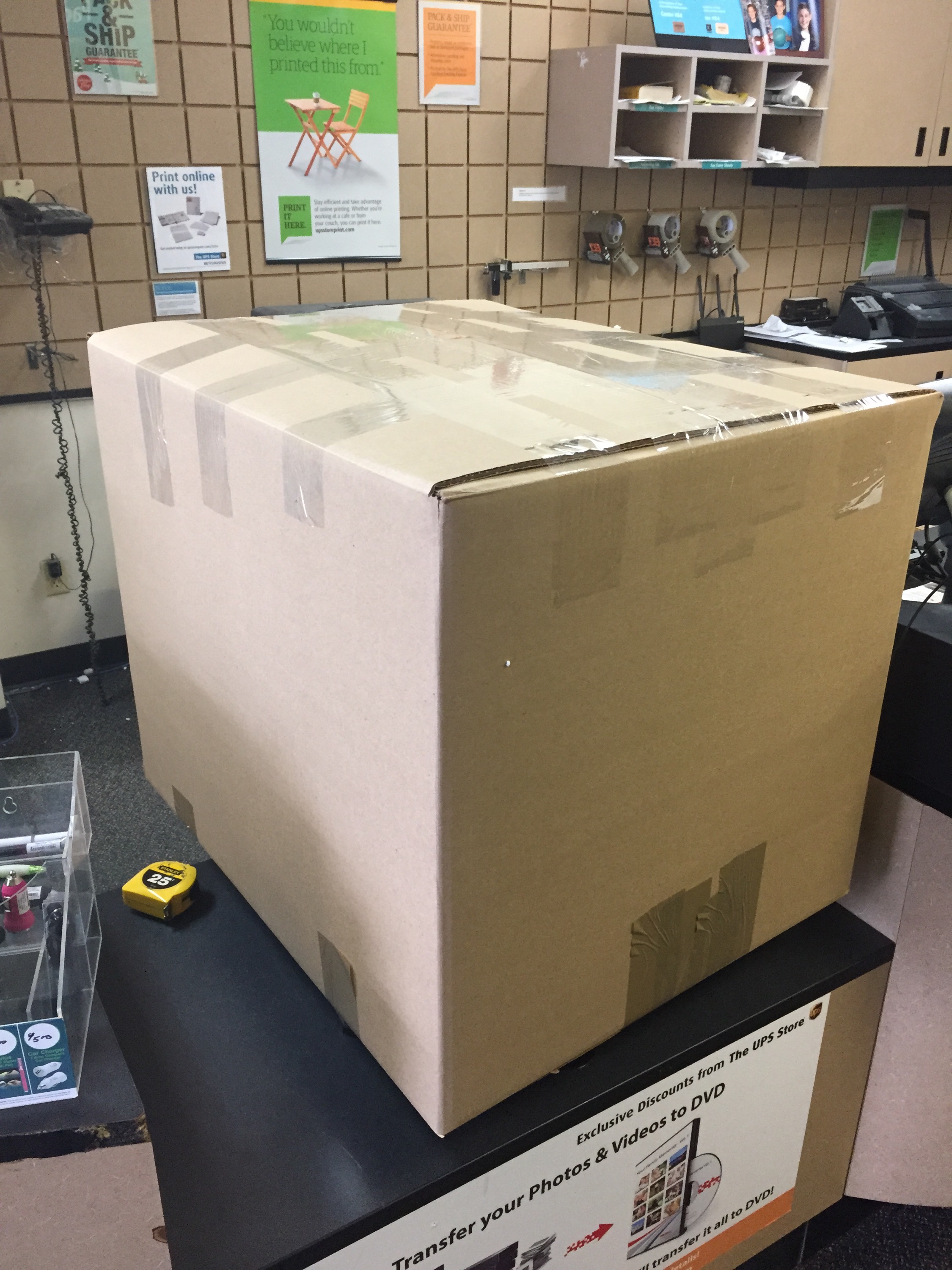
All this to say, there are a few things that make this a difficult machine to troubleshoot. So I cheated. I bought a 3rd, working unit. It arrived exceptionally well packed (so very grateful for that), with a nicely made interconnect cable (I already had a factory one), and it worked as advertised. Finally, I was able to see this beauty in action!
But I said I was going to fix a 230, so I set about starting to swap cards, this time, with a known good unit.
Swapping the Clock & Synchronizer Cards made no change. This supported my suspicion that perhaps they weren’t getting the right signal from the memory circuit. Swapped the memory, no change. The Start / Stop comparators send signals back to the clock, so I tried those next.
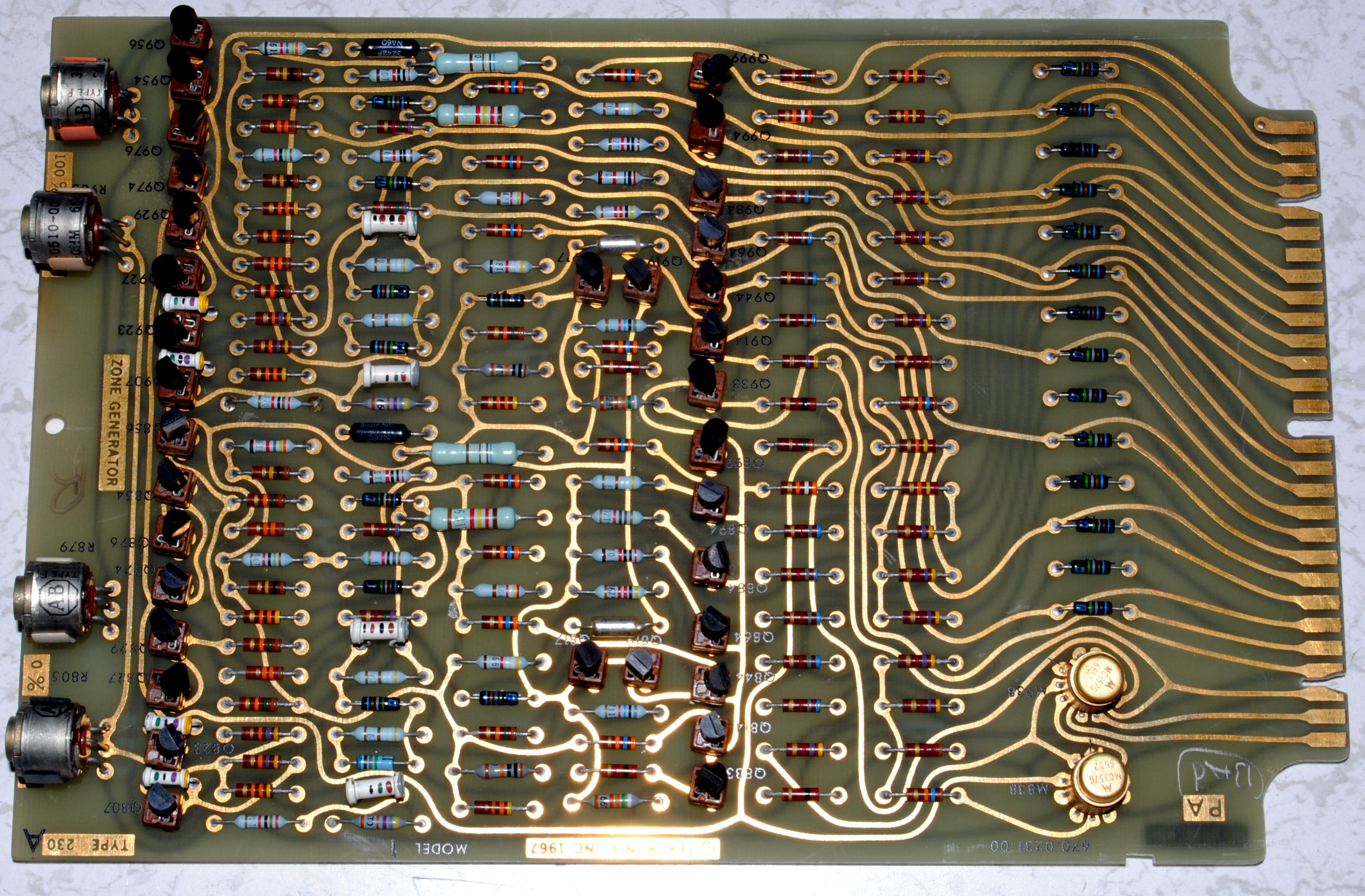
It’s always the last thing you try. With the B channel Memory & Zone Generator, I swapped the A Zone Generator with the known good card, and the unit spring to life. Through mechanisms I’m still trying to understand, if you have a bad Zone Generator Card installed with a good memory card, it can lock up the unit into the state I’d been seeing it in. And as luck would have it, I had three bad zone generator cards.
The Zone Generator Card has (2) logic ICs, and 36 transistors, a mix of NPN & PNP, all individually socketed.
The sockets are a blessing and a curse; It’s easy to swap transistors, but the sockets themselves also become a point of failure.
Sometimes, you want to sit down and dig into a schematic, come up with a hypothesis on why it’s not working, and start probing around to prove or disprove your theory. Other times you just want to brute force a problem, because it’s 11:00 PM, and manual labor is sometimes easier than critical thinking. So I set out to test every transistor in one of the bad cards to see if I could coax it back into the living.
I believe these to be unremarkable transistors, since the application is mostly simple low speed switching. In my model there was a mix of Tek model #s and manufacturer #s: NPN: 2N3904 / 151-0190 PNP: 2N3906 / 151-0188 I decided to test them on my 575 Curve Tracer at their operating voltage, fearing that perhaps the chinesium battery powered one might miss a fault, since these are operated across 50V rails. I found 2 culprits:
And with those replaced, the unit sprung to life!
So now we have 2 Zone Generator cards that at least let the unit run measurements, but both have problems. The Zone Generator card generates the areas on the displayed waveform where measurements are made, and show those at highlighted portions on the trace. A zone can be .5cm, 2cm, 4cm or 10cm long (or 12cm, but I’m not getting into that now). When the zone is .5cm, the average of that zone is returned; when it’s longer, the peak is returned.
The first card had an issue where the 0% zone would jump around, and not get to all the locations. We can see in the schematic, there’s a binary coded input coming from the zone position control. Because of the way it was jumping around, I suspected either the 2 or 4 bit, corresponding to Q864 or Q884. Q864 was bad, and replacing it gave me a fully functioning card.
The second card had an issue where the entirety of the 100% zone would be highlighted, so I could only see a movable cursor when only the 0% zone was selected.
This trace shows 2 good ZONE signals, and the incoming SWEEP GATE on the bottom, which I’m triggering from (thank god for 4 channel scopes). The negative pulses represent the position and width of the two zones.
The trace below shows a bad ZONE signal.
I’m seeing this signal coming from M938, but also going into it. Moving upstream, I check Q933. That’s OK. I pull and re-seat M938, and that seems to fix the issue. Now I have a cursor, but it has the same skip issue as the other card. The 100% zone transistors in question are Q964 & Q984. Both of these are good, but re-seating them fixes the issue. Like I said, those sockets are a blessing and a curse.
So now I have 2 more working Zone Generator cards, and a 2nd mostly functioning 230. It’s still wildly out of cal, and there are some quirks with the Nixie display, and cross channel time measurements, but I’ll get to those eventually.
This is a continuation of an effort started a few years back. I had purchased one of these off eBay, but found that only every other bit would get stored. The troubleshooting steps in the manual indicated that this meant either a bad A3 buffer or A4 controller card. Although the schematics are included, there are no board-level troubleshooting instructions, or detailed theory of operation. Furthermore, HP says to not even return these boards for repair, simply discard them and they will send replacements. I because they’re made up of inexpensive 74LSxx series chips, even back in the late 70’s when the device was built, it would not be economically viable to have a technician spend their time diagnosing and repairing these boards. Yet that’s what I’m going to attempt.
When I first dug into this, I soldered dozens of little jumpers of magnet wire to various pins so I could probe the inner workings while the card was inserted. This got me nowhere, and so I shelved the project.
A year or two later, I saw another one come up on eBay, and one it for a surprisingly reasonable sum. It was listed “as-is, for parts”, but I figured I’d take the risk. Although in worse physical shape, this unit actually was fully functional. So now armed with a set of working cards, I was able to troubleshoot the bad unit.
Swapping cards, I was able to confirm that A3 was the problem. Fortunately, this card is accessible in place if you remove the HPIB (GPIB) card, which will not hinder operation. This finally let me probe the device in action.
The A3 board is essentially the edit buffer. Bits are read in, displayed on the front panel, edited, and then placed back into memory. The read & write is done serially, so there’s a shift register made up of 7474 flip-flops, and 7451 And & Nor gates that allow for the bits to be modified. The circuit is split up into even & odd sections, each with their own clock, serial in & out lines, and a few other control signals. (note the odd symbol for a NOR gate in the schematic below).
I first suspected the the flip-flops, so I unsoldered all of them, and installed sockets. I tested them in a little chinesium chip-tester, and one of them was bad, but the problem remained. I turned my attention to the and / nor gates, which unfortunately my little tester didn’t support. I wired up my 16500 Logic Analyzer to the output of each of those gates, and found that U32 was glitching. After replacing that I had what seemed like two working units.
Maybe this happened during repair, or maybe it was an issue that I didn’t catch at first, but now on the second unit (the one I thought was perfect), The 16th bit now mirrors the 2nd bit, on all words. This problem seems to follow card A4, which is not accessible when installed. It’s also a more complex circuit.
A4 card, partial schematic
I flipped the unit on it’s side, so I could start probing the edge connectors. On the analyzer, I’ll designate the last pin on the pod as PROBE, so I can move it around looking for interesting signals. When I find one, I’ll add a grabber to the next free line on the pod, and add it on the trace. I have it in continuous capture mode, to trigger on the clock signal (which only runs during a load or fetch). I turned my attention to J1-8 & J1-5, which are odd & even lines out to the RAM card. I expected them to look similar, but they don’t.
The odd line, which is working, seems to be in phase with it’s clock (this is showing no bits active), while the even one looks different.
I expected to see a similar pattern as the odd line on both lines of the good unit. I was wrong.
It looks totally different. Not shown here, but when there are bits selected on the bad unit, I’m seeing short glitch pulses on both the odd & even lines. Those are not evident on the working unit.
So without being able to dig deeper into the circuit while it’s working, I’m at a bit of a loss. For the time being, I’m going to be content with one working unit and one parts unit.
I decided the next step would be to build an extender card so I can freely probe both good & bad units while in operation. The edge connectors are 3.96mm pitch (?!), and I found 4 on eBay at a reasonable sum. They’re right angle connectors, but I’ll make ’em work. The bigger annoyance is there are jumper cables between cards along the top, so I both need to make an extender for those to connect to card A4, and I need to accommodate cables that need to pass across A4, without having to extend a bunch of other jumpers. I think I’ll design this card with a large enough hole in it. It’ll be mildly annoying, and I think a job left to Future Paul (screw that guy…).
I’ve been putting this off for a while, but after a series of easy wins, I thought maybe I was up for the challenge. I have had in my possession for a number of years, a decent collection of analog sampling plugins and accessories from Tektronix, including 2 digital readout units, which allow for automated voltage and time measurements. Getting those readout units working is the goal, but first I have to start with a reliable sampling system.
I’m doing all this on a tektronix 568 mainframe, which has all the connectivity for the readout and automation systems, but these plugin pairs would work just as well on a 561 or 564 if you just wanted basic sampling functionality.
First I’d like to catalog the state of all of these plugins. I think the majority of them don’t work, so I want to find the units that work the most, and start from there. If I have a working pair, it will help evaluate the other plugins, as sometimes it’s hard to tell if the fault lies in the timing unit or the sampling unit.
The plugins
3S76 – Dual Sampling #2443 This one seems to work on the A channel. I have had it successfully send a trigger to the timing unit, and was able to position a signal on screen. The B channel is not working. After some time, I do get a sweep on screen for it, but I can’t position it. Getting the B channel working might be a good step in understanding how repair other sampling units. More on the repair below.
3T77 – Sweep #2810 This seems to work. Needs trigger sensitivity up pretty high, and it’s not what I’d call rock solid, but so far it seems like the best timing unit of the lot.
3T6 – Programmable Sweep #110543 This also seems to work well. External trigger provided on BNC J123 on the rear of the 568, via the gremar connector on the plugin
3T77 – Sweep #2250 Doesn’t work.
3T77 – Sweep #0881 Doesn’t work.
3T77 – Sweep #2246 Doesn’t work.
3S5 – Programmable Dual Sampling #40199 This seems to work on the A channel with the 1 known good S2 sampling head I have. The B channel is not working Side note: the channels are lettered on these early sampling scopes, and numbered on traditional scopes. No idea why, but it holds true on the 661, and all of the 560 series plugins. On the 7S14, it’s back to numbers.
3S5 – Programmable Dual Sampling #30151 A channel works, with internal triggering. The B channel is not working.
3T2 – Random Sweep #30320 Doesn’t work.
3S76 – Dual Sampling #1209 Doesn’t work. With normal/invert switches set in the middle (a troubleshooting step in the manual). I get a sweep that can be moved vertically on Channel A, but not on Channel B, suggesting there are a few things wrong with this unit. The sample diodes seemed to pass a multi-meter diode test, for what that’s worth.
Update: I stole a Nuvistor V1073 & transistor Q2163 from this to repair #2443
3S2 – Dual Sampling #40267 Both channels work, although I wasn’t able to get internal triggering working. Unfortunately I only seem to have one working sampling head at the moment.
3S76 troubleshooting
Set up with plug-in extender Waveform at test point 4Waveform at test point 6Measuring bridge voltage on channel A – all good. Measuring bridge voltage on B channel – no goodSampling diode bridge
A collection of notes & research on the HP 16500 series logic analyzers. I’m buying one in a few days, and trying to understand the differences between versions, and the myriad of features & options.
I believe I’m getting the following configuration:
16500B Mainframe
Hard-disk (the owner says he added, and thought that made this essentially a C model, but that’s not quite true)
Network option (not sure which one)
(1) 16530 400 Megasample per second (MS/s) scope timebase
There’s a lot of documentation, and the mainframe and cards have their own manuals. Generally, everything has a User Guide, a Service Guide and a Programmers Guide. The mainframe also has a Setup Guide & a User’s Reference. The User’s Reference covers the basic operation of the mainframe itself. Unfortunately, the only available PDF it has a font issue, making it very difficult to read.
To understand how to use the logic analysis & oscilloscope functions, refer to the manuals for the cards themselves.
The 16500L card gives you a 15 pin AUI jack, for which an adapter (or Media Access Unit) is required for 10Base-T Ethernet connectivity.
The 16500H card has an RJ-45 jack built in, as well as the expansion card connector (also on the 16500L?) and a “High Speed Port” for connection to the 16505A Prototype Analyzer (is this SCSI?)
The 16500C has an RJ-45 jack built in. X-windows connectivity is supported on the B & C models, but only later cards are fully supported. For example, earlier scope cards will have a visible interface, but won’t show their trace; only the 16532A Oscilloscope Module will.
Programming via LAN can either happen via sockets at port 5025, echoing commands to \system\program over NFS, or copying a file containing a list of commands to \system\program.
16500B & 16500C both run a Motorola 68EC030, per their Service Guides. One of the links above claims that the ‘B’ runs a 68020
Hard Drive
Turns out the hard drive on this unit is no good (got a few bucks off because of it). These machines are of the IDE era, and the list of supported drives is small, and mostly Quantum Fireballs. Ko4bb’s page seems to have the most comprehensive write-up, and I already have a Syba SD-CF-IDE-A adapter on the way. I’m hoping a 128MB CF card that I already have lying around will be supported, but I’ve also ordered a 256MB card that was explicitly on Ko4bb’s list.
Other things to look at
16505A Prototype Analyzer.
16534A 2GS/s, 500MHz dual channel scope (no extra timebase card needed)
16521A 48 channel pattern generator (I don’t know if this works on it’s own, or is only an expander to the 12 channel 16520A).
First Light
I opened it up, gave it a good cleaning, and reseated all of the connectors. It was mentioned that the hard drive may be problematic, and so is the touch-screen.
With the mouse connected, I get an ‘Impaired’ error about the touchscreen, but it seems to work.
The hard drive does not work
I can boot off either the original Composite System Disk or the hand-made ‘boot disk’, but in either case, none of the cards are recognized, and it doesn’t even see the network card.
I believe the mainframe need to see the modules for the installed cards on the boot disk, so lets see about making our own.
If I make a copy of the boot disk by copying files in windows I get an error on boot.
Windows complains about formatting a floppy
The mainframe can format floppies. I’ve had mixed success – it formatted one floppy fine, and whined about another one after having just formatted it.
I was able to boot with a disk I made by formatting on the mainframe, and copying files over from Windows, however I’m still seeing unrecognized cards.
I removed all but one timebase & one scope card, and still not recognizing the cards.
Hard Drive, revisited
The original hard drive finally spun up to life after a number of reboots and I got a few days of playing around with it until the parts came to replace the drive. I largely followed the instructions on Ko4bb’s page, but had a few difficulties:
When copying files (individually, unfortunately) from the floppy to the drive, you have to go into the name field, and hit clear so that it automatically picks up the name of file. If you don’t do this, it still has the name of the last filed you copied, and you’ll end up writing over it.
I had a hell of a time getting file writes to stick at first. My first few attempts gave me an empty hard drive upon reboot. I wasn’t sure if it was a bad card, or my process (I followed the instructions), but what finally worked was a combination of the last CF card in my inventory, and rebooting after formatting, and then rebooting again after making the /SYSTEM folder, just in case. That did the trick and I am now able to boot off the CF card to the latest OS.
Touchscreen
The ‘impaired’ status was ultimately fixed by removing the face panel and cleaning off the bezel on both sides, and brushing off the IR emitter / receivers. One of the links above incorrectly states that this is an acoustic touchscreen – it’s not: It’s an IR grid, similar to some Tek scopes of the same era. Works great now.
Pod interface
I’ve got this connected up to the RC2014 bus with the flying leads into a strip of header pins, but it’s not something I’d like to repeat. Instead, I should build a breakout board. This guy made some inline adapters for various 8 bit platforms, but hasn’t updated his site with any detailed info.
Here’s the pod pinout, from this post that also has some cool X-rays of the pod and leads.
There are no electronics in the pods, but there is an RC network in the probes. I’m clearly not the first person who wanted to connect their logic analyzer to a board without using a bunch of leads, and HP has a whole document detailing their series of connectors and accessories dedicated to just that. This document describes an isolation network that should be built into the connector interface, and is I believe pretty much what’s in the probe body of the flying leads.
This is also the circuit in the isolation adapters, which reduce down to a 20 pin connector. If these are available cheap enough, it may be better than soldering a bunch of SMD resistors & caps.
The plus side is there only 12 – 15 bucks each, the downside it’s it’s more dangley shit hanging off the board, with a fragile flex PCB lead, and more connection points. Still, it saves a hundred SMD components.
Update – new cards arrived
the owner contacted me and said he found some other cards:
Unfortunately, none of the new logic analysis cards work with the existing one, in so much that they couldn’t stack to add channels, rather they’d function as their own separate logic analysis engine. I could stack the two 16510B cards for a total of 160 channels, albeit at a rather anemic sample depth & speed, or I could use the 16550 for 102 channels at 500MHz, but still shallower depth than what’s on the 16555. Ideally, I’d get another 16555 card, which I might if the price was right.
Definitely looking forward to messing with the pattern generator though!
Currently Installed:
A: 16520A Pattern Generator
B: 16531A 2 channel 100 MHz Oscilloscope
C: 16530A Oscilloscope Timebase
D: 16550A 102 Channel Logic Analyzer
E: 16555A 68 Channel Logic Analyzer
In storage:
(2) 16510B 80 Channel Logic Analyzer cards
(2) 16531A 2 channel 100 MHz Oscilloscope cards
Ideal Configuration
A: 16555A 68 Channel Logic Analyzer
B: 16555A 68 Channel Logic Analyzer (bonded to above)
Thanks to Alex C who pointed out that if you’re using multiple 16555A cards, you need to be mindful of the setting of the Master jumper – as if they’re both set to master, the mainframe gets confused. See the manual for the jumper settings.
The basement clean-out continues, and today I bid farewell to a Viking Valiant, a 160M – 10M AM transmitter good for 200ish Watts. It’s big, heavy, and full of tubes. I picked it up at a ham-fest over 20 years ago. It was a fixer-upper then, and nothing has changed. The face-panels is a little rough around the edges, but the logo, meter, knobs, and most of the markings are intact. The coils, tubes, and variable-capacitors are in good shape, and there aren’t any signs of oozing goo from any of the transformers. This baby is ripe for a restoration, and it’s about to get it’s chance.
These were available from the mid 50’s through the early 60’s and could be purchased as a kit, or fully assembled. A very nice gentleman in Texas won this auction, and I do hope he posts some pics & notes of his restoration process. I can say in my limited dealings with people on eBay that folks who are technically knowledgeable and really understand what they’re buying are generally a joy to deal with. I stipulated that anyone contact me before bidding so we could discuss the shipping logistics, which I think helps ensure a smoother sale for items like this. Someone contacted me and asked if the transmitter supported SSB; I’m glad he didn’t bid.
What follows are the pics I took for the eBay sale, as well as pics I took while packing, to give an idea of what’s involved in packing an 80 pound transmitter full of rare vacuum tubes.
High power RF is a beautiful, black art to me.
This mechanism is kind of cool: at certain points in the front panel knob’s rotation, the pins in attached plate mate with an angled groove in the block attached to perpendicularly mounted rotary switch.
First, take out all the tubes and individually wrap each one in bubble-wrap. I didn’t mark the location of individual tubes – he’s doing a full restoration, he can figure it out. I did however make sure to group the 6146 tubes as they were installed, just in case they were matched somehow.
The tubes get packed in a separate box, lined with bubble-wrap:
layers of bubble-wrap between each layer of tubes, keeping the tubes away from the edges of the box.
Then the transmitter gets wrapped:
Then boxed:
I slipped another box over this (not shown). In the background:
– Tek Plugins, 1A1 & 1A4
– A Hickok rip-off of a Tek plug-in (subject of a future post) sitting on top of a…
– Supreme model 589 tube tester (my first tube tester)
– HP 606A .5 – 30MHz oscillator (Free to a good home)
– Eico tube-tester, hitting eBay tomorrow (my… 3rd tube tester?)
– HP Counter, which I’m totally keeping
– My very first ‘scope, the venerable Tektronix 545A
Then brought to the packing store where they put it in another box, with a rigid foam base, and surrounded by peanuts. The resulting box is gigantic, heavy, and unwieldily…but safe. There’s at least 2 layers of cardboard and 6″ of packing between the transmitter and the outside world.
I used about 200 feet in bubble-wrap when all was said and done, plus god knows how many gallons of peanuts in the double-boxing. It cost $190 to get both boxes from NY to TX, including the $25 he charged me for the double-box. This is a close approximation of what you may go through to ship an old Tek 500 series scope, although I don’t know if I’d feel the need to pull the tubes.. maybe just the bigger ones. In retrospect, I probably could have just left the 7 pin & 9-pin miniature tubes in place.
Posted on by wpadmin -- Last edited on February 21, 2016
Here’s a first look at my Hickok 156. This was intended to be an ‘all in one’ solution for a radio repairman’s bench of the era, combining both standard and frequency selective voltmeters, as well as a watt-meter, and monitor speaker. This newsletter has a great article by David Boyle, who restored his own Kickok 156.
I figured it was time to break this off into it’s own post. After some initial troubleshooting, I’d determined that the CRT was the source of the intensity and focus flickering I was experiencing.
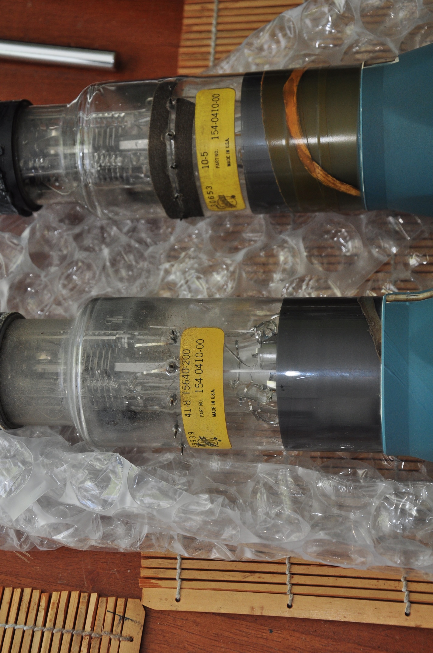
I ordered a replacement I found on eBay, and it arrived yesterday, safely and extremely well packed: Here it is after unbubblewrapping:
I proceeded to carefully disconnect and remove the old CRT, leaving a gaping hole in the business end of the scope:
Note the electrode connectors that press against pads on the neck of the CRT. in front of that is the trace rotation coil, wrapped around a black plastic bobbin.
I compared the two to make sure they were in fact identical. Spoiler alert: They’re not. The part# is the same, but there are other markings that differ.
OK though, same part number, we should be good, right? Hmm.. one of these things is not like the other:
There are 6 pads around the old CRT, and 6 corresponding contacts on the scope. The new screen is missing the 2nd (or 5th?) pad. Additionally, it looks like there’s a conductive trace coming out of the left of the 2nd pad on the old CRT that’s attached to the 3rd trace on the new one. I needed to do a little more investigation before I was comfortable just shoving in the new screen and hoping for the best.
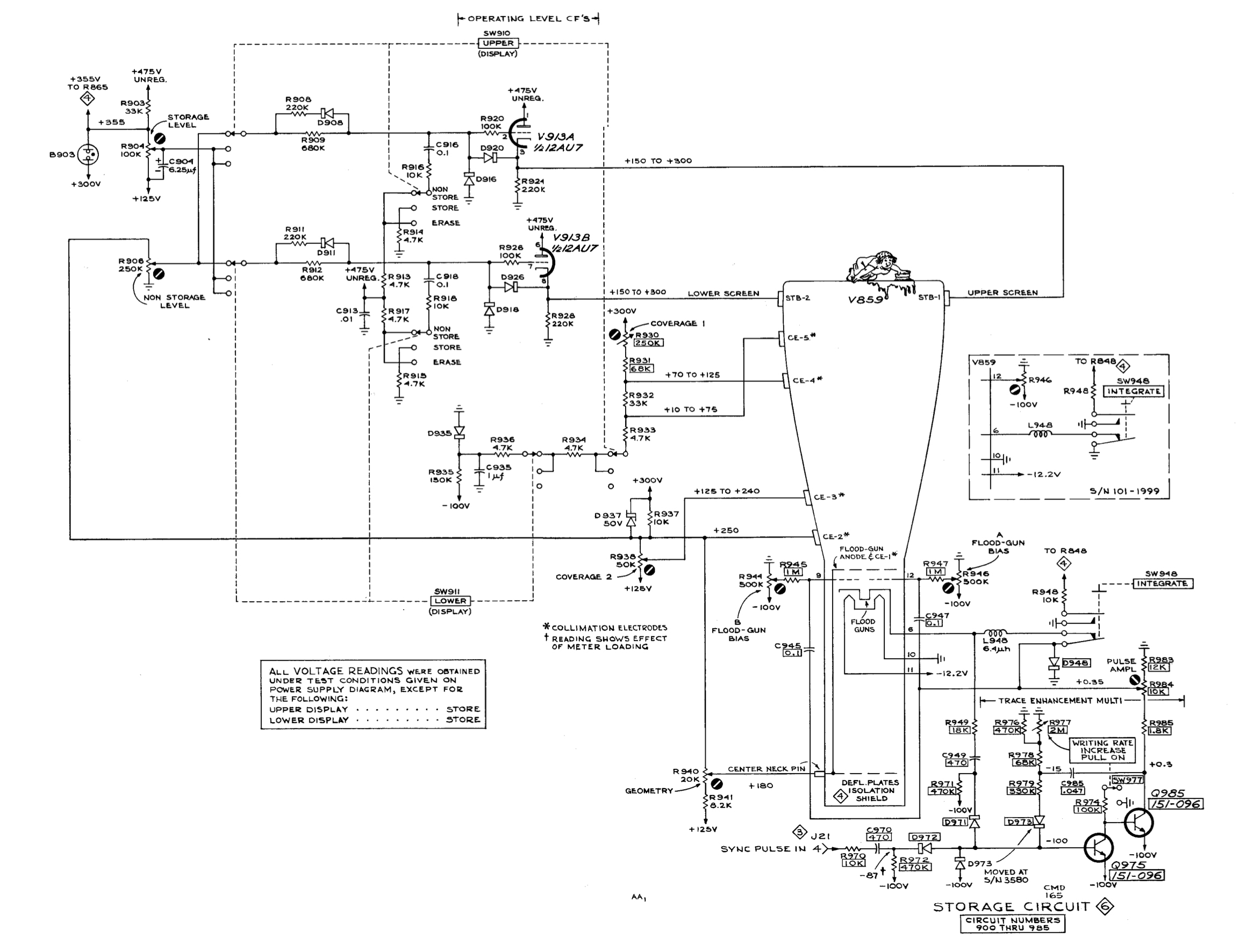
These connections are all a part of the storage circuitry, as seen in the schematic below.
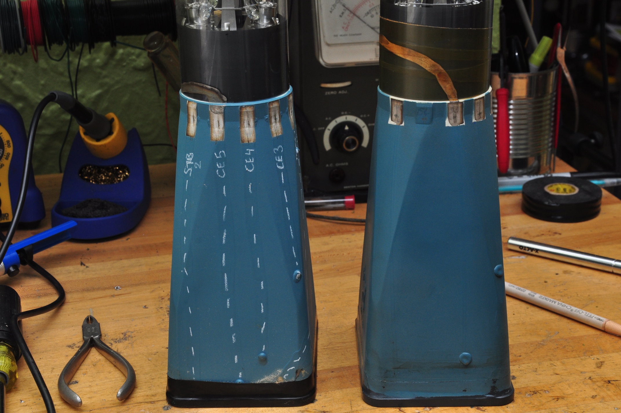
After a bit of cold metering in the scope, I was able to determine which connections were which on the CRT, and I marked them with a grease pencil:
So pins 1 & 6 (counting counterclockwise from the bottom in the scope) are STR1 & STR2, the upper and lower storage targets, while 2 – 5 are CE1 – CE5, the collimation electrodes. I’ve marked the path of the conductive traces so they’re more visible, you can see that they each terminate at the connection to their respective grids.
Feeling confident enough, I carefully installed the new CRT and brought it up slowly on the variac. I got a beautifully sharp trace that didn’t flinch, even with gentle taps on the tube:
As you can see, intensified mode works great.
One of my other recent purchases was a Heathkit TT-1 Tube tester. I started out the previous version diagnosing a smoking resistor in the storage section power supply. Now I had a way to check the tube. Both sides of the 12AT7 checked out OK on mutual conductance and shorts, but one side failed the grid current test (exhibiting lots of it). AH HA!!
I suspect the grid current was causing excessive draw on the 475v supply, which is why the resistor was overheating. I replaced the tube and slowly brought it up on the variac – low and behold the resistor remained cool.
Wait a minute, a 12AT7? The schematic (and nicely silkscreened chassis) calls for a 12AU7. Huh, I didn’t realize that upon first inspection. The 12AT7 has a much higher gain then the 12AU7, and I wonder if that led to the premature failure of the tube. It now has the correct tube.
Next on the hitlist:
Documenting the storage functionality. It sort of works, but needs some attention
Understanding the grid current test on the TT-1
Sourcing a replacement handle. I actually don’t mind going off-brand here, and would dig a custom replacement as long as it made use of the original mounting hardware.
Picked this up as a part of a larger lot, and was the first I attempted to power up. I did so stupidly, without a Variac. Quickly shut down after smelling smoke from R646, a 100Ω 1W resistor that’s a part of the unregulated 475v line. Metered it after the incident, and it appears to be OK.
Yanked the plugins and grabbed my newly re-wired Variac. as I rounded 50v, things started to spring to life – around 80v I got a spot on the CRT, and R646 was HOT. Shut ‘er down.
I think I’m going to yank all the tubes & transistors in the power supply, and check each supply one at a time, starting with the -100v supply. We start with the -100v because as with most Tek scopes of the era, the -100v (or -150v) supply was the one that all other supplies were referenced from. We’ll start with -100v, then +125v, then +300v. While the 475v supply is unregulated, it comes into close contact with some of the other supplies around the storage circuitry, which is also on the list of suspects. Just for a chuckle, remember all of these are considered ‘low voltage’ supplies 😉
With only the tubes in the -100v supply installed, I get -150v on the rail when line voltage is brought up to 115v. There’s about 90v across the gas regular tube instead of 80v. I’m not sure if this is because the 125v supply isn’t up? Furthermore, what’s with the pin 6 connection on the regulator tube?
With V667, V674 & V654 reinstalled, I can get the -100v power supply dialed into -100.0v.
Attempted to dial in the +125v supply but it jumps between 123.7v & 126v as I adjust the pot. 125.9v was as close as I could get it. Getting the +300v rail dialed in was no problem, same with the -12.2v supply.
420v unregulated reads 427v, 475v unregulated reads 485v with 115v line voltage.
Now I’m suspecting the problem is in the storage circuitry, since that appears to be the only thing powered from the 475v supply. As a side note, are these tin whiskers?
OK, with V800 & V814 installed, I get a spot on the CRT! Focus & astig controls change the spot shape, and location on the screen. When I get it as sharp as I can, the intensity control also makes the beam move around. Lets try a horizontal plugin.
SUCCESS! Lets try the vertical plug-in.
It needs a cal and cleaning, but all 4 traces seem to work somewhat. Even the delayed sweep seems to work:
So the trouble is in the storage circuitry.
After running for a while, the intensity started to jump around, became very bright, and the intensity control no longer functioned. Stay tuned for more…
10/12 UPDATE
it’s general intermittent intensity issues, stemming somewhere from the HV supply.
C830 & C832 measured around .0026u which correlates to the parts list, but not the schematic, which calls them out at .0068u
R842 ((2)2.7M+(2)3.3=12M) Measured 13M cold, measured open after about 15min operation, then slowly dropped the meter picked it up around 50M, and it’s almost all the way back down. Some metering in the early minutes after shutdown leads me to suspect one of the 3.3M resistors.
there’s a strong mechanical component to the problem; lightly pressing on the HV portion of the central chassis would drastically affect the intensity of the trace.
metering across the two neon bulbs I’d see anywhere between 50v & 120v that’s directly affected by the intensity control. In one flicker scenario, the intensity wavers but this voltage remains consistent. After being warmed up for about 20 min, the flickering would affect this voltage, causing the neon lights to fire
11/1 UPDATE:
I was wrong about the resistors, they read OK when immediately lifted from the circuit after power-down.
I’ve measured the HV supplies, and they seem consistent during the focus & intensity flickering, though measuring them does affect the trace (which I was surprised would happen with a 75MΩ probe impedance).
Screen voltage of V800 is around 65v for a normal trace at .2ms and can jump as high as 90v during a full bloom event.
As per the recommendation of Albert on the forum, I checked the V800 screen w/o the CRT connected, and it was around 65v.
Gently tapping on the chassis above the HV terminal strip does accentuate the issue, but I can’t find a component (either tube or passive) that responds specifically to some more directed tapping. I’ve re-seated the CRT socket, but it seems those wires are particularly sensitive to giggling. I opened up the the socket, and the pins look good.
It turns out tapping directly on the CRT shield or neck causes the biggest change in intensity, so now I’m fearing it’s a mechanical problem with the CRT. I can wiggle the CRT or leads to get a good trace, but it quickly goes back to incessant flickering. This is getting really frusturating. I think the only fix might be:
1) Sourcing a new CRT
2) Hitting it with a brick until I feel better
UPDATE: There’s a replacement CRT en route, part # 154-0410-00 (P31 phosphor, same as mine). CRT replacement chronicled here
Picked this up about a year ago, and used it solely with my then slightly misbehaving 7D01, in combination with the DF01 Display Formatter. Because the DF01 was gen’ing all the characters, I never noticed that the readout feature was misbehaving until I went to use a pair of conventional plugins.
There’s a few things wrong with this:
1) The characters are incorrect
2) The top and bottom of the vertical plugin readout are supposed to be for channels 1 and 2 respectively, but they both seem to respond to channel 1 only.
Regarding the incorrect characters, it appears that from this table, the characters are shifted one to the left of what they should be. ‘0S’ should read ‘1V’, and ‘4m’ should read ‘5u’ Columns and rows are selected by way of a current loop between the plug-in and mainframe, using .1ma steps between 0 & .9ma.
Oh, hello:
“Score!” I thought, but sadly turning it does nothing. Also, my columns are the issue, not the rows. UPDATE – Column Match doesn’t do anything either.
So I started poking around with my 7D20 and found something strange coming out of the U3433, the custom timer chip:
Note the often overlooked screen annotation feature on the earlier 7k scopes 😉
So there should be a negative going pulse on pin 16 that corresponds to the waveform on pin 10. Also note that negative portion of the waveform on page 10 are shorter where the pin 10 pulse is missing. I went ahead and ordered a replacement U3433, we’ll see if that does anything. In the mean time, I’m off to the tek message board…
09/16 UPDATE:
Heard back form a gentleman on the forum:
1) What I’m seeing on the output of U3433 is not uncommon and due to display skip (which is described in the manual, I just have to wrap my head around it)
2) He recommended swapping U3429 row decoder & U3418 column decoder – did that, no change.
3) He recommended swapping U3232 row data switch and U3263 column data switch. oh fuck, those are BURIED. Standby for some fun.
9/16 UPDATE:
The power supply slides right out, making U3232 & U3263 accessible. Well played Tektronix. Swapping them made no change.
Here’s the bottom of the scope – note the plastic rails on the bottom of the PS on the left. One of those was loose and keeping the PS from sliding out. Had to pop the bottom cover off to free it.
resocketing a few of the transistors fixed the missing readouts on the left horizontal bay, and the upper/lower duplication I was seeing. Now every bay has it’s readout, it’s just wrong.
9/17 UPDATE:
what’s supposed to be +4.4v on pin 9 into column decoder U3418 is only +3.84v
what’s supposed to be +14.5v on pin 10 is 14.8v
9/19 UPDATE:
Well, this has suddenly turned into a larger problem. Yesterday I’d gotten some of the characters to change by paralleling in a decade substitution box. Today I tried again but paralleled the wrong resistor (R3418), and I as was trying to pull the lead (live – dumb) I shorted something, heard a snap from the power supply, and the display went crazy, then dark. I shut it down, and when I started it back up, U3447 started to release it’s magic smoke.
I can only suspect that one of the legs of the power supply has gone awry, but the power supply wont fire up when not under load. I’m at a complete loss as to what to do next…
OK – moving on from despair…
With the readout board fully disconnected, the scope powers up and behaves normally (sans readout). IMPORTANT NOTE: When disconnecting the mini coax connectors, note that some of them have shield potentials of 15v, so take care to make sure they don’t touch the chassis.
9/20 UPDATE:
It was U3401 – zeros logic & memory.
I decided to swap out one chip at a time from the 7834 to the known good 7603, in order to asses the damage. When I got to U3401, the same problem showed up on the 7603. Total facepalm for not doing that earlier. All other chips were OK, with the exception of U3418, the column decoder. So now I’m down:
U3418 Column decoder – tek part 155-0014
U3401 Zeros logic & memory – tek part 155-0018
U3477 7402 quad 2 input NOR gate – I only have an 74ALS02, not sure if that’ll cut it.
Replacements for U3418 & U3401 en route
9/20 UPDATE:
74ALS02 is fine for U3477, tried it in the 7603 (thanks David)
In retrospect, I should have suspected U3401 given that ‘>’ worked but ‘IDENTIFY’ didn’t, since it’s U3401 that signals the column & row data switches to run through the sequence of characters to spell ‘IDENTIFY’.
9/25 UPDATE:
After an in situ check of components around the affected areas, I pulled U3418 & U3401 from the 7603 and installed them in the 7834, held my breath, and power’d it up. All good. The soon-to-arrive replacements will make the 7603 whole again, though for now it doesn’t really matter, since it’s really only host to my 7D20 & 7D01.