I’ve been putting this off for a while, but after a series of easy wins, I thought maybe I was up for the challenge. I have had in my possession for a number of years, a decent collection of analog sampling plugins and accessories from Tektronix, including 2 digital readout units, which allow for automated voltage and time measurements. Getting those readout units working is the goal, but first I have to start with a reliable sampling system.
I’m doing all this on a tektronix 568 mainframe, which has all the connectivity for the readout and automation systems, but these plugin pairs would work just as well on a 561 or 564 if you just wanted basic sampling functionality.
First I’d like to catalog the state of all of these plugins. I think the majority of them don’t work, so I want to find the units that work the most, and start from there. If I have a working pair, it will help evaluate the other plugins, as sometimes it’s hard to tell if the fault lies in the timing unit or the sampling unit.
The plugins
3S76 – Dual Sampling #2443 This one seems to work on the A channel. I have had it successfully send a trigger to the timing unit, and was able to position a signal on screen. The B channel is not working. After some time, I do get a sweep on screen for it, but I can’t position it. Getting the B channel working might be a good step in understanding how repair other sampling units. More on the repair below.
3T77 – Sweep #2810 This seems to work. Needs trigger sensitivity up pretty high, and it’s not what I’d call rock solid, but so far it seems like the best timing unit of the lot.
3T6 – Programmable Sweep #110543 This also seems to work well. External trigger provided on BNC J123 on the rear of the 568, via the gremar connector on the plugin
3T77 – Sweep #2250 Doesn’t work.
3T77 – Sweep #0881 Doesn’t work.
3T77 – Sweep #2246 Doesn’t work.
3S5 – Programmable Dual Sampling #40199 This seems to work on the A channel with the 1 known good S2 sampling head I have. The B channel is not working Side note: the channels are lettered on these early sampling scopes, and numbered on traditional scopes. No idea why, but it holds true on the 661, and all of the 560 series plugins. On the 7S14, it’s back to numbers.
3S5 – Programmable Dual Sampling #30151 A channel works, with internal triggering. The B channel is not working.
3T2 – Random Sweep #30320 Doesn’t work.
3S76 – Dual Sampling #1209 Doesn’t work. With normal/invert switches set in the middle (a troubleshooting step in the manual). I get a sweep that can be moved vertically on Channel A, but not on Channel B, suggesting there are a few things wrong with this unit. The sample diodes seemed to pass a multi-meter diode test, for what that’s worth.
Update: I stole a Nuvistor V1073 & transistor Q2163 from this to repair #2443
3S2 – Dual Sampling #40267 Both channels work, although I wasn’t able to get internal triggering working. Unfortunately I only seem to have one working sampling head at the moment.
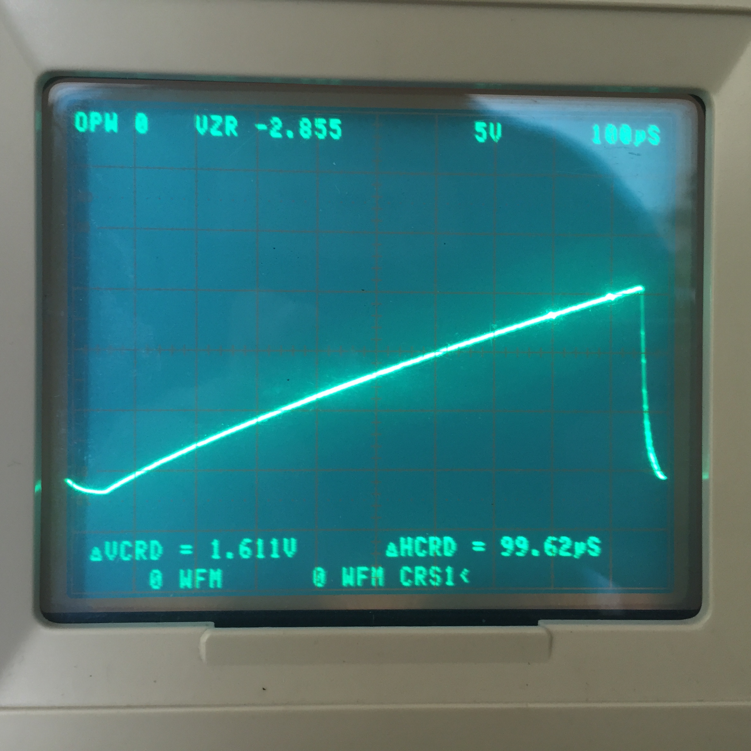
3S76 troubleshooting
Set up with plug-in extender Waveform at test point 4Waveform at test point 6Measuring bridge voltage on channel A – all good. Measuring bridge voltage on B channel – no goodSampling diode bridge
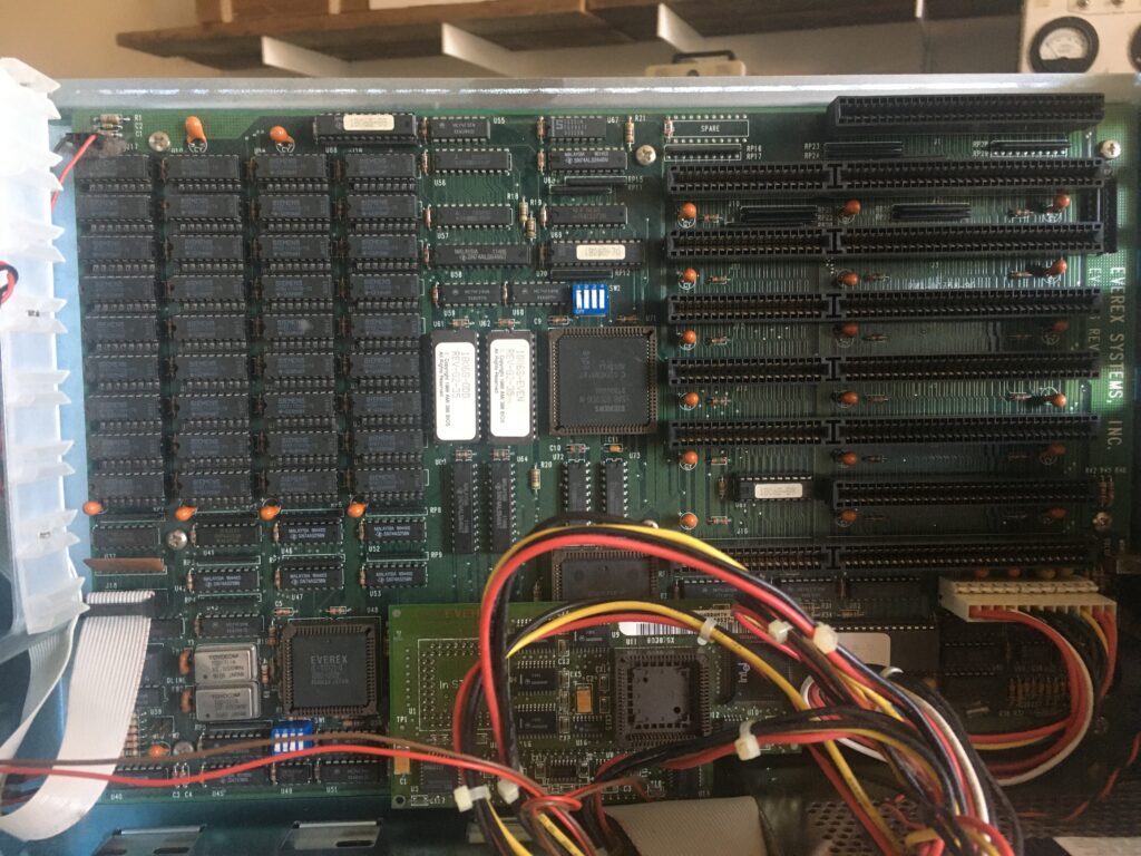
Aaaand, I let another year go by without posting. I suck. Next on the bench – an old 386 computer. I’ve been in the mood to poke at one of these for a bit; last time I had one was squarely in the 90’s and I was running linux on it (probably slackware, maybe redhat).
It boots successfully into BIOS, and has a great front panel character display. I’m going to disassemble it to get part #s off all the components.
Motherboard: EV-1806 Rev G Turns out this is a 286 motherboard, and what makes this a 386 is the Everex InSTEP daughtercard.
The daughtercard plugs into the the 80286 & 80287 sockets. It has a 80386SX-16 soldered on, and a PLCC socket for an 80387 (which is annoying, since most I’m finding on eBay are PGA).
There is a 5 1/4″ and 3 1/2″ drive, a Teac FD-55GFR and FD-235HF respectively. A cursory search seems to indicate that the 3 1/2″ drive is High Density, so I’m going to make a plain old 1.44Mb DOS bootdisk.
The Drive Controller is An Everex EV-346M. It supports (2) floppy drives from 360kB to 1.44MB, and 2 MFM hard drives. It says only ST506/ST412, but I’m wondering if that’s really the case. I’ve got a pair of ST 225 drives that I might want to try out. Worst case, I’ve got a few other controllers. I was surprised to find an MFM controller; I thought IDE drives were commonplace by the mid 90s.
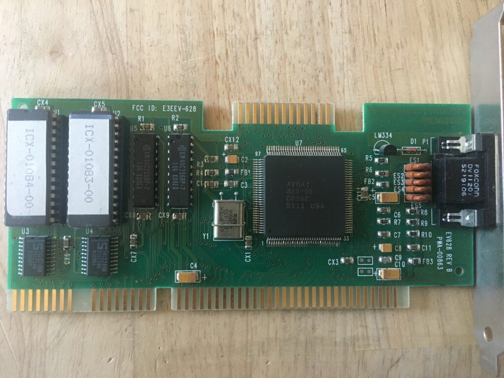
The Video Card is an Everex E3EEV-628. Not really sure there’s anything to say about it?
I made a DOS 6.22 boot disk, but the way it’s set up, the 5 1/4″ was the A drive. Just flipping the cables so the 3 1/2″ didn’t work -the disk light came on, but still got the classic ‘non system disk or disk error’.
So lets look into the dip switch settings on the 3 1/2″ Ah – there’s a DS0 & DS1, and DS1 was jumpered, so lets switch to DS0. No apparent change. I really need to brush up on floppy drive wiring, but I’m going to beat on this blind for a bit more. I don’t actually know if this drive is any good, or if I’ve even made a bootable disk. Yeah, so I’m an idiot – I tried just copying the files over onto a floppy disk (I’m on a mac), but in doing so, you have no way of stipulating what ends up where; the BIOS starts executing from sector 0. It was able to make a bootable disk in a Win10 VM, and it got me to an A: prompt, but a DIR failed. I’m not entirely surprised. It turns out making an old school DOS boot disk is a pain in the ass in 2022. I found bootable images at Winworldpc, and am using a trial of WinImage to write the image to a floppy. I was able to boot into the DOS 5.0 setup disk, but it wanted me to set up to a hard-drive. I also couldn’t exit out of setup and resume it, or even run a DIR command. I need to find a good bootable, single floppy OS.
There’s something funky going on – I grabbed a 6.22 boot image from here, but I’m still not able to get a proper boot – it tries to load a CD rom drive and fails, and after that it tells me it can’t load COMMAND.COM.
I also tried an earlier version that looks like it’s a single 720k disk. I was able to write it using DD directly in MacOS. Mac even recognizes it as a 720k disk, and sees it’s contents, but it won’t boot.
Fuckit, let’s try linux? Trying Fdlinux. I’m not super crazy about seeing dd: /dev/disk3: end of device 2881+0 records in 2880+1 records out Seems the latest version expects you to do some tricks to format a slightly larger drive, but the previous version seems to fit on a standard disk. I finally at least got a meaningful error from LILO (remember LILO?!): Error 0x80. this is a disk timeout, suggesting an issue with either the drive or the media. So it’s time to try either another drive, or a damn gotek, I guess. I appreciate floppies from a nostalgic perspective, but I’m remembering just how much they suuuucked.
3/3 Update:
Yeah, the floppy drive was bad. Goteks (with flash floppy) are great for permanent install, but I’ve got a Lothartek HxC SD that’s great for troubleshooting. I got this with an Atari ST a few years back, and it’s an old model; the only thing to watch out for is that the SD card has to be formatted FAT16. This is easily accomplished on Mac OS with: sudo newfs_msdos -F 16 /dev/disk3
I was able to boot into DOS, and hooked up a Seagate ST-225 20MB MFM drive. Fdisk was unable to add a partition, however a low level format using Speedstor seemed to do the trick. It’s a great utility, and honestly I need to refresh my memory on what a low level format is.
4/2 Update:
Hard Drive I was excited to find that I’ve got a working MFM drive, but decided to save it for a machine that might really need it. I had in my stash, a no-name IDE & Floppy drive controller, so I decided to see if I could get that to work with a CF card. Because the BIOS is so decrepit, I wasn’t able to get it to work. Enter XTIDE – an alternative BIOS that supports more modern drives. I was able to burn the 8k AT version onto an EPROM, and install it into a no-frills network card. Through a combination of dumb luck and wizardry, it actually freakin’ worked: After the built-in BIOS runs, XTIDE runs and lets the machine see the CF card. DOS was able to format it and install on to it. And since it’s just a FAT16 formatted volume, I can yank the CF card and put it in a reader to do bulk copies of software.
Floppy I replaced the bad 3 1/2″ drive with a Gotek running FlashFloppy. There’s a bunch of different flavors of “goteks” out there, and they have different methods of flashing the software. For this one, I needed an USB A to A cable, and had to run some utility in Windows. Works fine now.
Math Coprocessor I installed a 387 Math Coprocessor. Linux now gets a little further into booting, but still hung. I’ll play around with this some more some day.
BIOS Battery I got tired of having to go through setup every time, so I cobbled together a CR3032 battery mount for it.
Next Steps:
Network Card Can I find drivers for it? It’s a Racal InterLan, and thanks to this page, I was able to figure out how to use an EPROM with it. It claims it to be an NI5210 card, and I found what looks to be drivers that match on Archive.org, but I haven’t figured out how to install them.
Soundcard A soundblaster AWE64 Value is what I’ve got – it’s not the best card for this setup, but it works OK. Installation went fine, you just need to install the S64Basic Driver, and make sure that you’ve already expanded the CTCMBSS folder, which contains the plug-n-play drivers that the installer will ask for.
I recently picked up a somewhat rare 3A5 auto-ranging plugin for the 560 series, and decided to fire up my 564 to test it out. Since it had been over a year since I powered up my 564, I tried it first in it’s current config, a 3A72 Dual Trace plugin, and a 3B3 Timebase. Two problems were readily apparent:
The varying intensity – I strongly suspect this has to do with AC ripple, since it holds steady when line triggered
The trace is about 2 CM short.
Here’s a table showing measured supply rail voltages & ripple. All voltages are within spec, but the ripple on the -100 V, 125 V & 300 V lines are out of spec.
Rail
DC Voltage
Ripple
-100 V
-100 V
120 mV
125 V
125.5 V
40 mV
300 V
301 V
120 mV
-12.2 V
-12.21 V
2 mV
355 V
357 V
420 V
435 V
1.5 V
475 V
493 V
280 mV
-3,300 V
-3,290 V
8 V
Replacements:
-100 V: C640, a combo 340uF & 10uF 200 V Electrolytic
+125 V: C642, a combo 340uF & 10uF 200 V Electrolytic
+300 V: C644, a combo 340uF & 10uF 200 V Electrolytic – this is only a 200V cap since it’s low side is off the 125V supply.
+475 V: C646 2x 40uF
So that’s a rebuild of 3 cans. C642 & C644 should take care of the ripple on the +420 V unregulated rail, which feeds the high voltage supply.
Using a fluke 6kV probe into my 7854 scope, I was able to measure about 50 V of high frequency ripple on the 3,300 V supply, however I’m not 100% certain that measurement was accurate. I could pick up about that much just by having the probe within a few inches of the HV supply, so I’m not sure how much of that was inductive pickup through the probe, or even the cable of the probe? I’d love someone to set me straight on that.
Following some recommendations on this old post on the tekscopes group, I gave the ceramic binding posts a thorough cleaning with IPA & cotton swabs. So far, I have not seen the intensity modulation problem return that didn’t seem to eliminate the problem, as it returned the next day, albeit not immediately, but after 30 or so minutes of operation. I did discover that with the cover reattached over the HV transformer & diodes, I was no longer able to detect the HF ripple when measuring high voltage. The AC ripple still disappears as soon as it’s measured.
Replacing C342 & C344 greatly reduced the ripple in the 125 V & 300 V supplies, but did nothing for the ripple on the 420 V unregulated, and hasn’t fixed this intensity modulation issue (I was pretty sure it wouldn’t though). I have confirmed that the intensity modulation is at 60Hz, and isn’t related to any errant signals from the horizontal plug-in by running the vertical plug-in in the horizontal plug-in’s slot, and feeding it a 60Hz ramp. The issue reoccurred.
As for the sweep length on the 3B3 – For now I was able to get the trace to the correct length using the sweep length adjustments pots, however, I had to crank them both (the normal and delayed sweep) fairly far clockwise. Once adjusted to the correct length, I do get sweep waveforms as documented in the manual, so I don’t suspect that I’m compensating for a problem further downstream.
Beam Intensity
There are, I believe 3 distinct different methods to modify the beam’s intensity:
J21-14: Intensifying Pulse – changing the intensity of the beam by altering the ground reference of the control grid supply
Taking a quick detour from oscilloscope repair to attempt to fix a RAM error on an Akai S900 sampler that I just scored for cheap. The two issues were a dim backlight, and RAM error “Bad RAM Bit DK09”
the logic board – check out that honkin linear power supply
Thanks to DOSputin for compiling a reference of what codes refer to what chips here. The best copy of the service manual can be found at this page, along with a wealth of other info on the S900.
DK09 refers to IC62. This thread confirms that there’s no way to test them all at once; you only get one bad ram message at a time, which means you have to take the whole damn thing apart, change the ram, reassemble it, then do the test again to find out where the next problem is.
Someone has been in this unit before. 3 of the 6 screws to attach the voice board were missing. It appears someone had dealt with a RAM issue before, as IC60 is now socketed. I’d planned on doing the same. After replacing IC62, I get another error: DJ12 – IC57. Fortunately, that was it, now the RAM test passes.
The latest firmware is V1.2C. I have V1.2A. I don’t think this matters, as I boot to what’s either called OS2 or OS4 with a floppy.
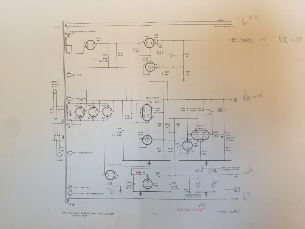
Well, after 4 years and two moves, I’m finally back at this old beast. I’ve chronicled my previous work here, and where I left off was getting a sharp, swept trace, if I disconnected the +225V line from the upper deck where the Vertical circuits are. There are some leaky caps up there, and with them in the circuit, they pull a bunch of other things low, including the HV section (I don’t remember why, but it made sense at the time).
This is now a SEVENTY YEAR OLD machine, and given that every Black Beauty & Bumble Bee capacitor I’ve come across so far has been the cause of trouble, I think the best course of action is simply to replace all of them.
After changing / checking / reforming every cap on the upper deck, I still was having problems with the +225V supply, so I turned my attention back to the regulator. It turned out that the series pass tube wasn’t working: All of the current was flowing through the bypass resistors, so the voltage level was based only on the current. I confirmed this by pulling the Series pass tube (6AS7), and noted no change in the behavior. Working back from the voltage trim-pot, I discovered that the 12AX7 comparator wasn’t working properly. The socket needed some cleaning, and then the whole thing locked right up at 225V.
So, it “works”! Here it is triggering at 10MHz
Issues:
Sweep linearity: going to change out the bumblebee caps in the timing circuit to see if that helps.
Sweep magnifier all sorts of weird.
Interplay between vertical position & vertical attenuation controls: need to look into this more – The ‘Vertical Attenuation’ control affects the vertical position of the trace. Not sure if this is supposed to happen or not, but I’d think not.
Change in intensity yields change in trace width: It seems to affect the horizontal trace width only, and happens in a counter-intuitive way; the trace gets wider when the image gets brighter.
Calibrator has an overshooting leading edge.
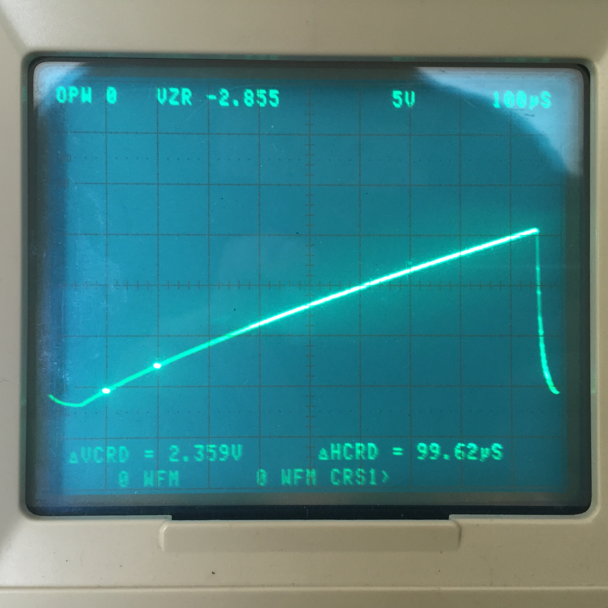
Sweep Linearity:
note the difference in slope between the beginning of the sweep waveform, and the end of it. Notice the difference in the slope between the start and the end of the sweep in the traces below. The worst of it was on the 100uS per division setting, and a new cap helped.
Sweep Magnifier:
the sweep wave form when sweep magnifier is turned on and swept through
C124, a .1uF bumblebee was the culprit. Replacing that, and restuffing C126, an electrolytic, solved the problem.
Calibrator The problem turned out to be, what pretty much every other problem in this scope was – a bad bumblebee capacitor. I’m just replacing all of them as I work across the scope; I replaced this one in passing, and the problem was gone on the next power up.
AC Socket I’ve never seen one quite like this before. It’s recessed, as are many of the later tektronix sockets, but there’s no ground pins, so the blades are centered. – Screw spacing = 1 1/2″ – Chassis hole diameter = 1 1/8″ – Socket inner diameter = 1″
According to some folks on the tekscopes group, these were not grounded, but rather accepted common extension cords of the time – searching used General Electric extension cords on eBay yields some good hits.
This picture from the 1952 catalog confirms their shape, and that the socket was not grounded. A member on the Tekscopes group says the manual instructs the user to ground the instrument via the front panel banana jack, but I couldn’t find reference to that.
If I wanted to replace it with a grounded alternative, I’ve got a few options:
an IEC cord – Would require some filing of the frame hole to fit, and may require some bodging of the steel case as well.
a powercon connector. may fit unaltered, at an angle, but might interfere with the back case, or require it to be modified.
midget twist-lock – 2 prong will fit, mostly unaltered, but the 3 pin would require opening the hole in the chassis, and re-drilling the mounting holes.
Here’s the drawing of the 3 pole midget twist-lock. I think this is the best compromise, as it doesn’t involve any adapter plates or square holes – just enlarging some already round holes by 1/8″. Incidentally, note the original date on that drawing. I appreciate that there’s a 55 year old drawing on a manufacturer’s site that’s still a current reference.
A collection of notes & research on the HP 16500 series logic analyzers. I’m buying one in a few days, and trying to understand the differences between versions, and the myriad of features & options.
I believe I’m getting the following configuration:
16500B Mainframe
Hard-disk (the owner says he added, and thought that made this essentially a C model, but that’s not quite true)
Network option (not sure which one)
(1) 16530 400 Megasample per second (MS/s) scope timebase
There’s a lot of documentation, and the mainframe and cards have their own manuals. Generally, everything has a User Guide, a Service Guide and a Programmers Guide. The mainframe also has a Setup Guide & a User’s Reference. The User’s Reference covers the basic operation of the mainframe itself. Unfortunately, the only available PDF it has a font issue, making it very difficult to read.
To understand how to use the logic analysis & oscilloscope functions, refer to the manuals for the cards themselves.
The 16500L card gives you a 15 pin AUI jack, for which an adapter (or Media Access Unit) is required for 10Base-T Ethernet connectivity.
The 16500H card has an RJ-45 jack built in, as well as the expansion card connector (also on the 16500L?) and a “High Speed Port” for connection to the 16505A Prototype Analyzer (is this SCSI?)
The 16500C has an RJ-45 jack built in. X-windows connectivity is supported on the B & C models, but only later cards are fully supported. For example, earlier scope cards will have a visible interface, but won’t show their trace; only the 16532A Oscilloscope Module will.
Programming via LAN can either happen via sockets at port 5025, echoing commands to \system\program over NFS, or copying a file containing a list of commands to \system\program.
16500B & 16500C both run a Motorola 68EC030, per their Service Guides. One of the links above claims that the ‘B’ runs a 68020
Hard Drive
Turns out the hard drive on this unit is no good (got a few bucks off because of it). These machines are of the IDE era, and the list of supported drives is small, and mostly Quantum Fireballs. Ko4bb’s page seems to have the most comprehensive write-up, and I already have a Syba SD-CF-IDE-A adapter on the way. I’m hoping a 128MB CF card that I already have lying around will be supported, but I’ve also ordered a 256MB card that was explicitly on Ko4bb’s list.
Other things to look at
16505A Prototype Analyzer.
16534A 2GS/s, 500MHz dual channel scope (no extra timebase card needed)
16521A 48 channel pattern generator (I don’t know if this works on it’s own, or is only an expander to the 12 channel 16520A).
First Light
I opened it up, gave it a good cleaning, and reseated all of the connectors. It was mentioned that the hard drive may be problematic, and so is the touch-screen.
With the mouse connected, I get an ‘Impaired’ error about the touchscreen, but it seems to work.
The hard drive does not work
I can boot off either the original Composite System Disk or the hand-made ‘boot disk’, but in either case, none of the cards are recognized, and it doesn’t even see the network card.
I believe the mainframe need to see the modules for the installed cards on the boot disk, so lets see about making our own.
If I make a copy of the boot disk by copying files in windows I get an error on boot.
Windows complains about formatting a floppy
The mainframe can format floppies. I’ve had mixed success – it formatted one floppy fine, and whined about another one after having just formatted it.
I was able to boot with a disk I made by formatting on the mainframe, and copying files over from Windows, however I’m still seeing unrecognized cards.
I removed all but one timebase & one scope card, and still not recognizing the cards.
Hard Drive, revisited
The original hard drive finally spun up to life after a number of reboots and I got a few days of playing around with it until the parts came to replace the drive. I largely followed the instructions on Ko4bb’s page, but had a few difficulties:
When copying files (individually, unfortunately) from the floppy to the drive, you have to go into the name field, and hit clear so that it automatically picks up the name of file. If you don’t do this, it still has the name of the last filed you copied, and you’ll end up writing over it.
I had a hell of a time getting file writes to stick at first. My first few attempts gave me an empty hard drive upon reboot. I wasn’t sure if it was a bad card, or my process (I followed the instructions), but what finally worked was a combination of the last CF card in my inventory, and rebooting after formatting, and then rebooting again after making the /SYSTEM folder, just in case. That did the trick and I am now able to boot off the CF card to the latest OS.
Touchscreen
The ‘impaired’ status was ultimately fixed by removing the face panel and cleaning off the bezel on both sides, and brushing off the IR emitter / receivers. One of the links above incorrectly states that this is an acoustic touchscreen – it’s not: It’s an IR grid, similar to some Tek scopes of the same era. Works great now.
Pod interface
I’ve got this connected up to the RC2014 bus with the flying leads into a strip of header pins, but it’s not something I’d like to repeat. Instead, I should build a breakout board. This guy made some inline adapters for various 8 bit platforms, but hasn’t updated his site with any detailed info.
Here’s the pod pinout, from this post that also has some cool X-rays of the pod and leads.
There are no electronics in the pods, but there is an RC network in the probes. I’m clearly not the first person who wanted to connect their logic analyzer to a board without using a bunch of leads, and HP has a whole document detailing their series of connectors and accessories dedicated to just that. This document describes an isolation network that should be built into the connector interface, and is I believe pretty much what’s in the probe body of the flying leads.
This is also the circuit in the isolation adapters, which reduce down to a 20 pin connector. If these are available cheap enough, it may be better than soldering a bunch of SMD resistors & caps.
The plus side is there only 12 – 15 bucks each, the downside it’s it’s more dangley shit hanging off the board, with a fragile flex PCB lead, and more connection points. Still, it saves a hundred SMD components.
Update – new cards arrived
the owner contacted me and said he found some other cards:
Unfortunately, none of the new logic analysis cards work with the existing one, in so much that they couldn’t stack to add channels, rather they’d function as their own separate logic analysis engine. I could stack the two 16510B cards for a total of 160 channels, albeit at a rather anemic sample depth & speed, or I could use the 16550 for 102 channels at 500MHz, but still shallower depth than what’s on the 16555. Ideally, I’d get another 16555 card, which I might if the price was right.
Definitely looking forward to messing with the pattern generator though!
Currently Installed:
A: 16520A Pattern Generator
B: 16531A 2 channel 100 MHz Oscilloscope
C: 16530A Oscilloscope Timebase
D: 16550A 102 Channel Logic Analyzer
E: 16555A 68 Channel Logic Analyzer
In storage:
(2) 16510B 80 Channel Logic Analyzer cards
(2) 16531A 2 channel 100 MHz Oscilloscope cards
Ideal Configuration
A: 16555A 68 Channel Logic Analyzer
B: 16555A 68 Channel Logic Analyzer (bonded to above)
Thanks to Alex C who pointed out that if you’re using multiple 16555A cards, you need to be mindful of the setting of the Master jumper – as if they’re both set to master, the mainframe gets confused. See the manual for the jumper settings.
While checking a 6EJ7 for my IM-21, I noticed a whiff of smoke coming from my trusty TT-1.
Per a suggestion of someone in the Vintage Test Equipment group, I turned to my trusty TU-75 and finally used it’s series bulb feature. An incandescent bulb in series acts as a current limiter, which both protects the Device Under Test, and gives a visual indication of when the DUT is trying to draw more current than you’d like. Sure enough, when the tube was connected using the ‘normal / disconnect’ switch, the lamp glows, and I see the voltage drop appreciably.
Side note: I finally got around to measuring and labeling the lamps in my TU-75. According to the wattmeter, the largest lamp is 500W! I seem to remember an even larger one that unfortunately got broken due to shoddy packing when I bought this 4 – 5 years ago.
What led me to the problem was this line adjust rheostat starting to smoulder.
See me. Spin me. Smell me.
It was suggested that this is not the source of the issue, rather an indication of something upstream drawing too much current. Hopefully not an underlying issue with the transformer. With 40 taps across a half dozen windings, It’s basically unobtanium.
I didn’t recall ever having an issue with this tester in the past, and sure, things age, but what’s different about this test than countless one’s I’ve done before. Well, for one thing, I don’t ever recall testing a tube with a 600mA before. I decided to try testing something with a fixed voltage filament instead. A 12AT6 with it’s 6.3V filament did not yield the same excess current draw, and tested fine under this setup.
Here’s another in-depth document on the TT-1. It references Kent’s document as well, and pages 12 – 15 describe the theory behind the ballast capacitor. The reactance is inversely proportional to the capacitance, so as the capacitance goes up, it’s equivalent resistance goes down. In my case, they’re all measuring a bit high:
Capacitor
stated value
measured value
error
C11
3.6 uF
5 uF
38%
C10
3.6 uF
5 uF
38%
C9
7.1 uF
11 uF
54%
C9 + 10 + 11
14.3 uf
21 uF
47%
The sum is what’s important for this range – looking at the switch, it appears that the capacitors are paralleled sequentially through the last three filament settings (the current settings). Is a 47% overage enough to account for this error? That would mean at 600mA, it’s theoretically allowing ~900mA: Not great, but I’m surprised it’s enough to cause this problem. There’s nothing else in this circuit – does this mean I should suspect a short somewhere in this tap? It’s the top-most tap of the filament winding, #29.
I’m going to try a lower current filament and see if I end up with the same issue, as well as some larger, higher current tubes.
Testing a 6L6 with it’s 6.3v filament at 900mA gets me a little bit of a dip in voltage down to 105V when testing with the dim bulb, but nothing like I was getting with the 600mA setting. With the bulb bypassed, it seems to work fine, and nothing is getting warm or stinky. Testing a 6HZ6 with it’s 450mA gets me a dip down to 80V. With the bulb bypassed, I get a good test, but started to get just a hint of fresh roasted components, so I killed it before I started to see smoke.
Went back to test a 6AW8 which calls for a 600mA, this time with a current meter on the common line on the ballast capacitor. With the bulb, the line voltage dipped down to 70V & the filament is only able to draw ~400mA. With the bulb bypassed, the filament drew ~700mA. I didn’t leave it on this setting long enough to summon the stank.
With the same tube & settings, switching to the 6.3V tap doesn’t cause the same brown-out.
My working theory is that there’s a short somewhere in the part of the winding that feeds the current filament settings, but that does not affect the other taps. Not being able to use the current settings actually isn’t too big of a problem, as the tubes that call for it also have a published filament voltage.
This is the first piece in a larger lot that I decided to tackle. It’s the simple cousin of the Heathkit IT-18, which also measured DC voltages & resistance.
I beat my head against this for far too long until I realized that the calibration pot would sway wildly out of spec depending on the position of the contact – from 40Ω to hundreds of ohms. I replaced it with a 50Ω pot and it was able to be calibrated to mostly within spec. I’ve never found these early, cheap VOMs to be particularly accurate, but they’re fine for basic work.
Posted on by Paul Carbone -- Last edited on June 20, 2020
Intro
This is not my first signal tracer, but it’s the first one I’ve gone to this much trouble on. These have been getting pricey ever since musicians discovered they make cute little practice amps, so whenever I see one at a good price, I’ll snag it.
When I got it, it ‘worked’. The indicator indicates, and sound played as expected. It had a bit of hum and noise – not unreasonable, but definitely room for improvement. At first, I thought I’d just replace any parts that were out of spec, but given how this is constructed, I decided a ground up re-build would be a better approach.
Here’s the before pic – the component count isn’t so high that it’s difficult to trace out in it’s condition, but it’s not exactly easy on the eyes.
Unbuilt Heathkits are getting fantastically expensive, but I figured if I did a complete tear-down, and ordered all new caps & resistors, I’d essentially get some resemblance of the new kit experience. So off I went ordering parts, and stripping the chassis.
Parts
Everything showed up as ordered, but I didn’t pay attention to the physical size of the resistors. Everything that showed up was 1/2 W as ordered, but they’re suspiciously small – even though they’re probably ‘correct’, they look out of place. They look like 1/8 W, they’re absolutely tiny.
The one’s in question are:
47Ω – on the output
10kΩ – in the power supply
470Ω – on a cathode
There’s also the 1W 1kΩ in the power supply (the one that was looking toasty in the original build). It’s bigger, but it still just doesn’t feel right. I’m going to go 2W on all these, somewhat for piece of mind, and somewhat for looks.
Wire
The solid-core for the wire used throughout measures .025 which puts it at 22 AWG. The OD w/ insulation is .056. I have a bunch of 24 AWG solid core PVC jacketed hookup wire in various colors, and some cloth covered 20AWG from New Old Sounds. The PVC wire has a slightly smaller OD than the original stuff, whereas the cloth covered stuff is on the thick side; slightly thicker than the transformer leads. 24 AWG is really fine for all of this, and I may use the cloth covered stuff for leads that pass through the deck. The highest current is probably the heaters. Each tube is 150 mA, and 24 AWG is good for 3.5 A, so we should be fine.
Color Coding
Most, if not all Heath gear of this era uses the same grey, solid-core wire. I’d like to impart some color coding, and a quick search unearthed this:
Ground = Black
Filaments = Brown
B+ = Red
Control Grids = Green
Plates = Blue
AC Line = Grey
Teardown
I was able to strip out almost everything, with the exception of the transformers and a few of their connections. There’s really no slack on the transformer leads, so I didn’t want to risk it.
Here it is as disassembled as it was going to get – note I already started on re-stuffing the electrolytic capacitor.
Speaking of capacitors – this one was a bear to empty out. I think it tested OK, but I was trying to make it future proof. In my experience, really dried out, dead electrolytics seem to come apart rather easily. When I opened this one up, it was still a damp, packed, impervious mess. Picking, poking, & drilling did nothing, nor did soaking in water. Boiling did the trick – a poor mans double-boiler with a sauce can kept me from exposing my cookware to the nasty innards.
Schematic
Tube compliment:
12C8 –
12SH7 –
12A6 –
1629 –
Rebuild
I generally followed the instructions, making a few modifications to component placement, particularly where smaller replacement components allowed for a neater layout.
Started with the twisted heater wiring
Power & fuse wiring
The face-plate was installed after getting a polish. It’s not perfect, but it’s better. The screw-heads & jack hardware also got hit with a wire wheel – It’s easy, and I think makes a big difference.
Face-plate installation
B+ Wiring
Coupling capacitors & plate wiring
Shielded cable
Shielded cable – termination detail
Upper Deck
Wiring up the eye tube socket
Final Assembly
I’m pretty proud of how this came out. There was one guy razzing me on the Vintage Test Equipment group about how some of the runs were too long & unsupported, which would cause variations in capacitance when they vibrate, or there was a possibility of exposed leads shorting if the unit was dropped. I’m dismissing those as non-issues; I’m not going to sweat variations in picofarads on a device that tops out at a few kilohertz, and any drop hard enough to cause these components to come into contact would have much larger consequences anyway. It may be difficult to tell from these photos, but leads that look close to touching are either at the same point in the circuit, or are a few cm away from each other. These construction methods aren’t appropriate for high frequency circuits, but for audio, it’s just fine.
Testing
With the final assembly complete, all that’s left to do is power this up, slowly on a Variac. It came to life with little fanfare – no creaks, pops, crackles, or smoke. Once I saw the glow of the eye tube, but didn’t hear anything, I was convinced I’d screwed something up – I expected at least a little noise. I tried playing back some music through the 1/4″ just for kicks, and was pleasantly surprised to hear clean audio reproduced. It’s sounds as good as can be expected for this tiny speaker, but it’s quiet and clean. I haven’t tested the wattmeter function – I may at some point, even though I’m confident it’ll never get used. The paint on the outer case isn’t in great shape, but I don’t have the means to strip it down, so that will be a future project – perhaps doing a whole batch in one go.
Well shit – it seems as though something else went wrong with this scope while I was slogging though the ROM problem. It’s not the display board. We’re not even getting to the point where that’s being checked. It seems to quickly go into this vegetative loop pretty much immediately. I put back the old (bad) ROMs to at least see if I could get the ROM error pattern again, but nothing – just all lights lit.
Did some probing on the chip-select lines on the ROM card, and it’s clear that it’s going through some quick little loop, but it’s not always the same loop on each restart. I’m hoping to find a way to reset the CPU w/o cycling power. I think I can short TP1200-1 to ground, but waiting for someone to confirm so I don’t invariably nuke something else.
I confirmed that all power supply rails are spot-on.