
Up next on the bench, a Simpson 476 Mirrorscope.
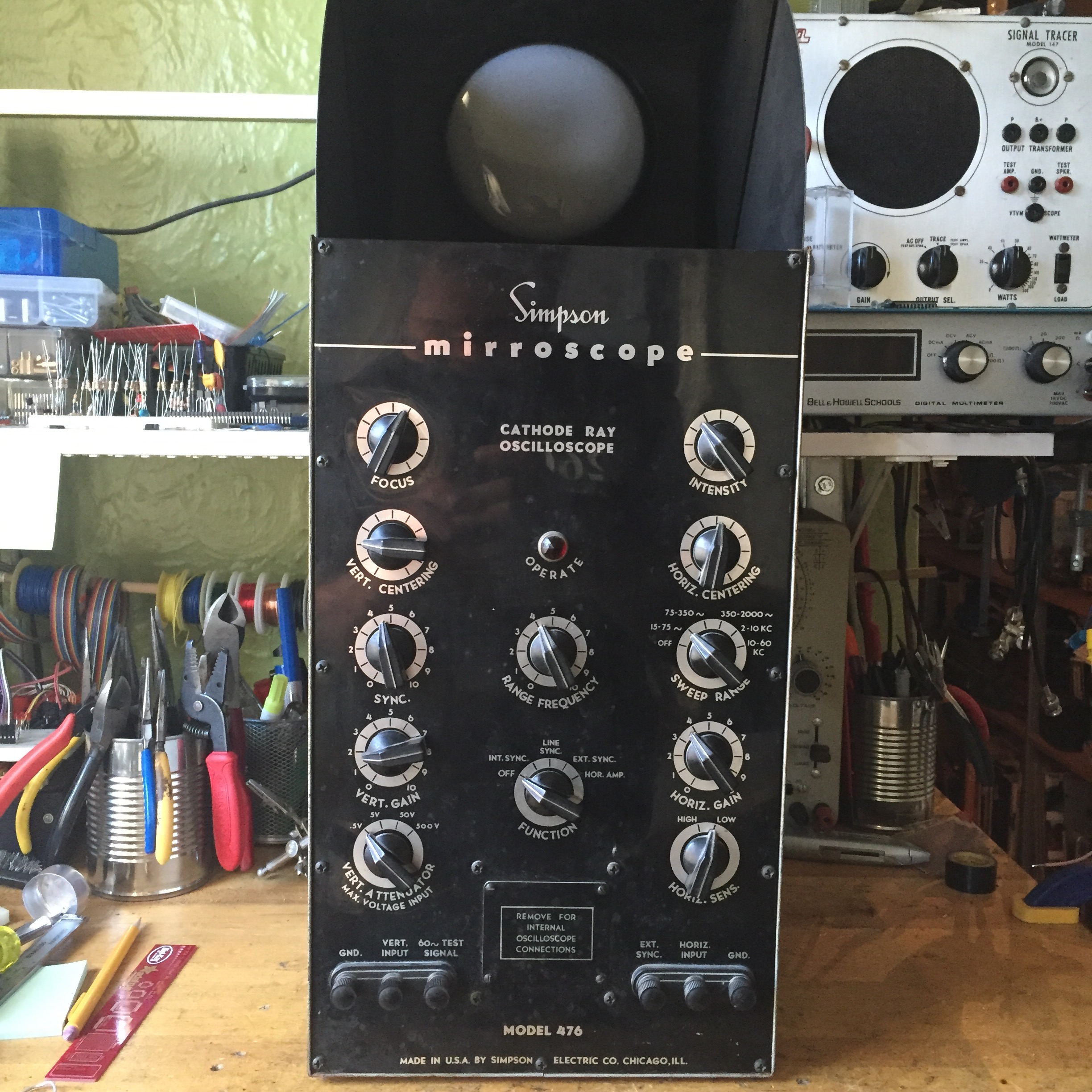
This example belongs to Benton Bainbridge, an NYC video artist. He’s got two, and this one needs the most help, so I figured I’d get it on my bench and get it working again. That’s the hope, anyway. As can be seen from the photo, the CRT points upward, and the operator views it through a 45° mirror, that flips up as the top of the chassis. This yields a benchtop oscilloscope at an unheard of depth of only 8″.
It turns out, the manual for this beast is no where to be found. I’ve reached out to Dave at Arktek manuals to see if he can dig up something. I’ve gotten hard-to-find manuals from him before, so hopefully he can work some magic. I also reached out to Steven Johnson, who’s got a great page and manuals for sale. The Simpson 480 Genscope is approximately one of these mirrorscopes with a signal generator on either end. I can’t even begin to imagine how unweildly that is to work on, but at least there’s a manual available.
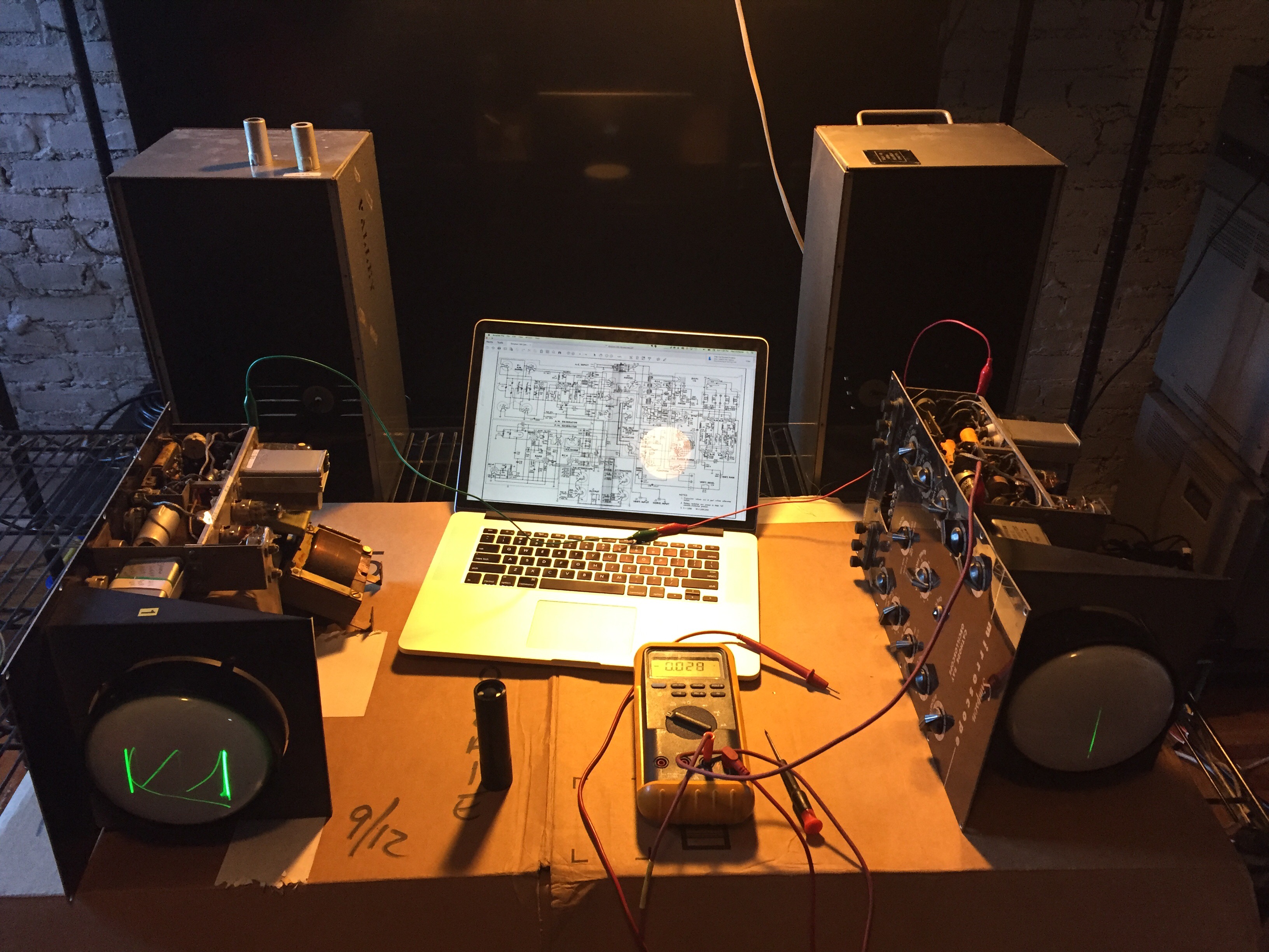
I met Benton at his place, and we started comparing the “good one” and the “bad one”:
Sweet DJ rig, yo
The problem seems to be in the vertical amplifier section, made up of (2) 6K6 twin triodes. One the good unit, the signal to the deflection plates varies between 170 – 240v while on the bad unit, they’re pegged at 350v, which appears to be full anode voltage. Tubes were tested, and swapped, to no avail. I brought my Heathkit TT-1, which Benton got a kick out of – it’s such a fun instrument to operate.
There were a few ground connections that appear to have been severed, but reconnecting them didn’t solve the issue. There are a number of resistors that are running hotter, so much so that they’re discolored; however when measured cold, they appear to still be in tolerance.
There are a few differences between the 480 and the 476:
- The 5Z4 rectifier is absent in the power supply. This appears to power only the oscillators, so no surprise there. The power supply consists of 2 6X4s, one for the CRT HV, at about 900v, and one for the rest of the circuits, at about 350v.
- There’s an extra 12AU7 not present in the schematics for the 480. I suspect this might be a pre-amp for the vertical input. The 476 has more rages than the 480: 4 steps from .5v to 500v as opposed to ‘low / high’ on the 480. Alternately, it’s a part of the sweep / trigger circuit? I know that this is scope is capable of ‘synchronized’ operation, but I can’t for the life of me see how this thing triggers by looking at the schematic.
- Some other component value differences.
Here’s the relevant part of the 480 schematic. 
Benton offered that I should take both, to have good one to compare with. I declined, only wanting to bring two additional cubic feet of oscilloscope into my apartment, but I may take him up on it if I can’t get this figured out. On old gear like this, I immediately suspect old caps in the power supply, but since the horizontal sections seems to be working (ish), that doesn’t screen out as the culprit. I think I’ll just start checking / changing out caps in the PS for good measure, as I familiarize myself with this unit.
The other thing I’m definitely going to do is grab my boss’s FLIR One to scope out any really hot (or suspiciously cold) components.
But before I do anything else, I gotta order some more caps, my HV Electrolytic stock is almost depleted. I kind of like running out of parts, it means I’m keeping busy.