Tektronix 514 – Back at it

Well, after 4 years and two moves, I’m finally back at this old beast. I’ve chronicled my previous work here, and where I left off was getting a sharp, swept trace, if I disconnected the +225V line from the upper deck where the Vertical circuits are. There are some leaky caps up there, and with them in the circuit, they pull a bunch of other things low, including the HV section (I don’t remember why, but it made sense at the time).

This is now a SEVENTY YEAR OLD machine, and given that every Black Beauty & Bumble Bee capacitor I’ve come across so far has been the cause of trouble, I think the best course of action is simply to replace all of them.

After changing / checking / reforming every cap on the upper deck, I still was having problems with the +225V supply, so I turned my attention back to the regulator. It turned out that the series pass tube wasn’t working: All of the current was flowing through the bypass resistors, so the voltage level was based only on the current. I confirmed this by pulling the Series pass tube (6AS7), and noted no change in the behavior. Working back from the voltage trim-pot, I discovered that the 12AX7 comparator wasn’t working properly. The socket needed some cleaning, and then the whole thing locked right up at 225V.

So, it “works”!
Here it is triggering at 10MHz


Issues:

  • Sweep linearity: going to change out the bumblebee caps in the timing circuit to see if that helps.
  • Sweep magnifier all sorts of weird.
  • Interplay between vertical position & vertical attenuation controls: need to look into this more – The ‘Vertical Attenuation’ control affects the vertical position of the trace. Not sure if this is supposed to happen or not, but I’d think not.
  • Change in intensity yields change in trace width: It seems to affect the horizontal trace width only, and happens in a counter-intuitive way; the trace gets wider when the image gets brighter.
  • Calibrator has an overshooting leading edge.
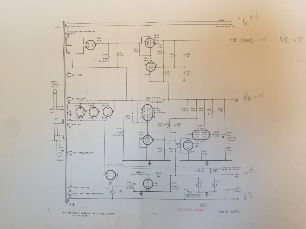
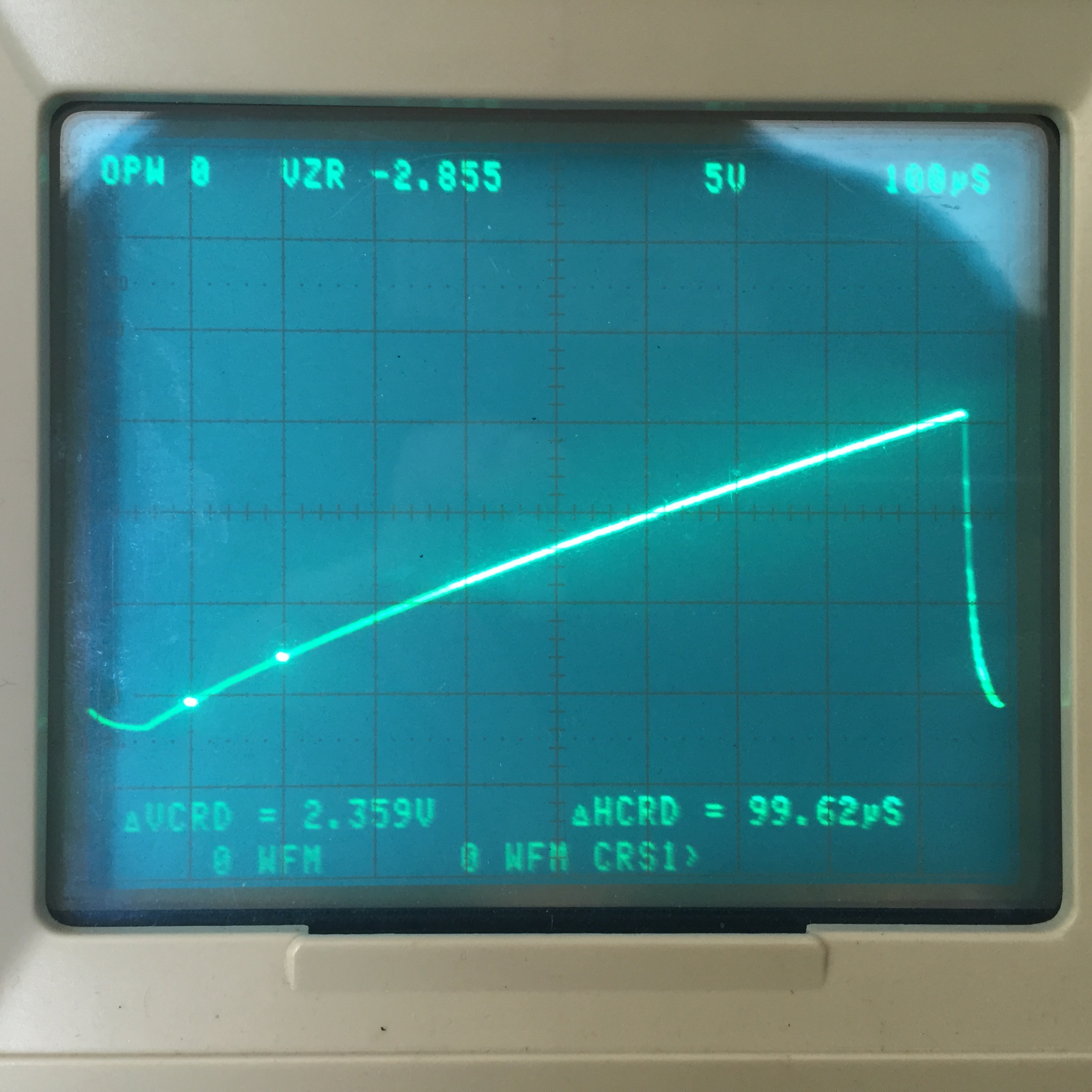
Sweep Linearity:

note the difference in slope between the beginning of the sweep waveform, and the end of it. Notice the difference in the slope between the start and the end of the sweep in the traces below. The worst of it was on the 100uS per division setting, and a new cap helped.

Sweep Magnifier:

the sweep wave form when sweep magnifier is turned on and swept through

C124, a .1uF bumblebee was the culprit. Replacing that, and restuffing C126, an electrolytic, solved the problem.

Calibrator
The problem turned out to be, what pretty much every other problem in this scope was – a bad bumblebee capacitor. I’m just replacing all of them as I work across the scope; I replaced this one in passing, and the problem was gone on the next power up.
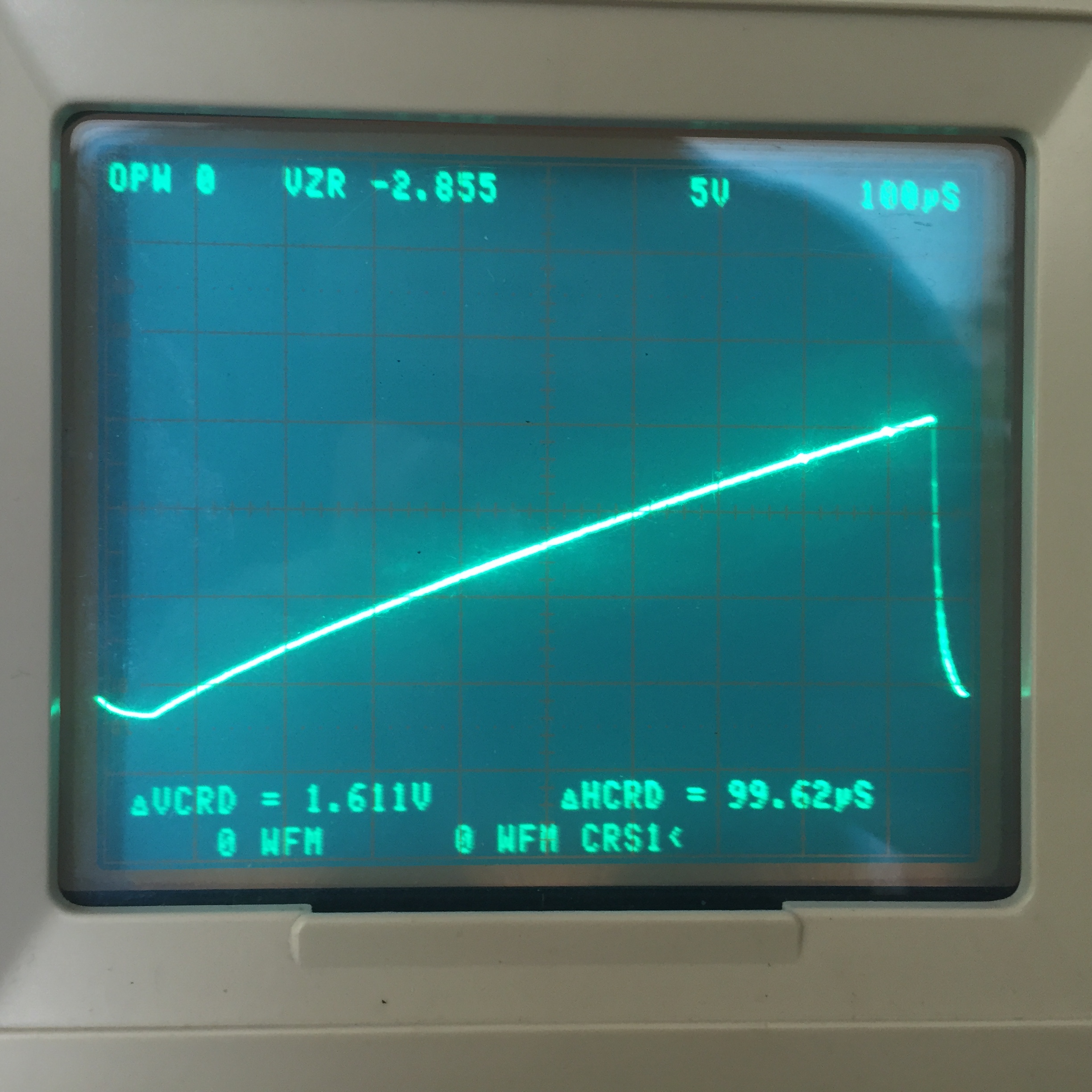
AC Socket
I’ve never seen one quite like this before. It’s recessed, as are many of the later tektronix sockets, but there’s no ground pins, so the blades are centered.
– Screw spacing = 1 1/2″
– Chassis hole diameter = 1 1/8″
– Socket inner diameter = 1″

According to some folks on the tekscopes group, these were not grounded, but rather accepted common extension cords of the time – searching used General Electric extension cords on eBay yields some good hits.

This picture from the 1952 catalog confirms their shape, and that the socket was not grounded. A member on the Tekscopes group says the manual instructs the user to ground the instrument via the front panel banana jack, but I couldn’t find reference to that.

If I wanted to replace it with a grounded alternative, I’ve got a few options:

  • an IEC cord – Would require some filing of the frame hole to fit, and may require some bodging of the steel case as well.
  • a powercon connector. may fit unaltered, at an angle, but might interfere with the back case, or require it to be modified.
  • midget twist-lock – 2 prong will fit, mostly unaltered, but the 3 pin would require opening the hole in the chassis, and re-drilling the mounting holes.

Here’s the drawing of the 3 pole midget twist-lock. I think this is the best compromise, as it doesn’t involve any adapter plates or square holes – just enlarging some already round holes by 1/8″. Incidentally, note the original date on that drawing. I appreciate that there’s a 55 year old drawing on a manufacturer’s site that’s still a current reference.

Tektronix 514: restoration update

A bag of parts from Newark arrived and I went to work replacing capacitors in the power supply.  First, I finished re-stuffing one of the cans:
IMG_5582.JPG IMG_5585.JPG IMG_5583.JPG IMG_5584.JPG

I’m really happy with how these came out.

Than went to work replacing the old bumblebee caps – here’s a few shots before I soldered and clipped the leads.  C102 is the re-stuffed can freshly installed.

IMG_5587.JPG

IMG_5590.JPG

I was conflicted about just ripping out old components and replacing them with new ones, but (and I’m paraphrasing his words from a conversation I had with Kurt): Tektronix used the best components they had available to them at the time.  If they had these newer, more reliable components, they would have used them instead.  You shouldn’t feel bad as long as the restoration is done in the spirit of the original design and keeps up with their level of craftsmanship.  I’m happy with my work so far and think I’m on the right track.

I decided to power this up on the variac.  It was almost midnight, so I didn’t bother with photos or videos, but:

I started to hear the whine of the high voltage power supply around 60 VAC on the input (frequency is around 4kHZ, wonder if this is right?).  Eventually I saw a fuzzy green dot on the screen around 80VAC, that quickly drifted off.  If I turn the intensity control all the way up, I see the familiar glow of on the screen you get when the beam is deflected way off the face.  All other controls are unresponsive.

The +1,500V supply is around 1,000V, the -1,500V supply is around -800V.  I would like to get those missing 1,200V back…  The -140V supply seems to regulate albeit somewhat loosely.  The 225V, not so much, and the 225V adjust control doesn’t do anything.  I’m suspecting I have to replace the reminder of the .01μF bumblebee caps in the supply.  Maybe I should just rename this hobby “replacing old capacitors”.

It’s a start!

514 Status update

A gaggle of capacitors is en route from Newark / Element14, so until they arrive, the 514 is off the bench.  I got enough to replace all bad caps in the power supplies, including the untested HV cans, just in case.  ‘High Voltage Problems’ is a common utterance when speaking about these old beasts, so I want to be prepared to replace anything.  I’ve been staring at the HV power supply schematic for the last week, and I think I’m ready to tackle it.  I got a enough 630v film capacitors in .1, .01 & .047μF to deal with bad bumblebee caps as necessary, as well as 22μF 450v electrolitics to restuff some cans with.

The plan is to replace all the bad caps I’ve identified, replace the rest of the missing tubes (which I have), then slowly bring it up on the variac.  I’m not expecting a trace, but I would like to see a spot, which would indicate that the power supplies are somewhat working.  after that:

  1. Check of all power supplies.
  2. Check the vertical signal path
  3. Get the sweep generator working
  4. Get it to trigger
  5. A thorough cleaning & make a new graticule

Tektronix 514: When are you from?

Here’s some of my notes about trying to understand a little bit more about the 514, in particular, mine (S/N 948)

The usual questions are:

  • When were they made and for how long?
  • how many different variants were there, and which were visibly different vs which ones were just internal revisions.
  • When is mine from, and which are the correct schematics?  Usually the schematics will indicate a range of serial numbers for which a particular schematic sheet is valid for.

Some of the things I observed in the manuals:

  • the schematics in the BAMA manual for this manual aren’t just raw scans, they’ve been re-composited.  It’s evident elsewhere in the manual as well.  Generally whoever put together the PDF manual did a nice job, but it appears they cropped out the serial number info when assembling the PDF schematic pages.  d’oh.
  • There’s a few pictures in the BAMA manual:
    1. TYPE 514 D CATHODE RAY OSCILLOSCOPE
                          SERIES “A”
      With the “serial” field on the bottom left of the unit.  Mine like this, except without the ‘SERIES “A”’ text. (no S/N shown next to “Serial” callout)
    2. TYPE 514AD CATHODE RAY OSCILLOSCOPE
      with the serial directly under that. (S/N #5181)
  • Comparing the BAMA schematics to the paper one I bought, I can confirm that the BAMA manual schematics are for S/N 3150 – 3408.
  • There’s a note in my manual that says:
    “Major circuit changes occurred in the Type 514AD oscilloscope at S/N 3409. Numbers in parenthesis indicate the earlier values in the Type 514D oscilloscope.”
    So the ‘A’ version is anything after 3409.  OK great.
  • But, looking at the versions of the vertical amplifier schematic, there is:
    1. “Type 514 / 514D Oscilloscope” S/N 101 – 3149.
    2. “Type 514 Series A Cathode Ray Oscilloscope”, S/N 3150-3408 (same one from BAMA) dated March ’53,
    3. “Type 514 D Cathode Ray Oscilloscope” S/N 3409+, dated March ’56, which has notes about changes in S/N 3650+
  • So it seems like there’s the 514, the 514 series A, and the 514A, all available with or without the ‘D’ for delay line.  The ‘Series A’ seems like it might be the precursor to the plain-old ‘A’ suffix, common of later models, but there’s some inconsistencies in naming conventions across the versions of schematics, so it’s difficult to be certain.  These are the earliest years of the company, so it’s not surprising to see evolution in the documentation.

Observations looking through the catalogs:

  • October ’50 514D is listed for $950.
  • August ’51 514D is listed for $950.  no ‘D’ in silkscreen.
  • March ’52: 514D is listed for $950.  Underside photo shows PS caps identical to mine, but ‘D’ looks like a part of the silkscreen.
  • March ‘53: catalog says there was a 514-D, but there’s no page for it.
  • August ’54: there was -AD only
  • August ’55: gone.

The punchline:

  • Made from 1950 – 1956
  • Mine is from somewhere between ’50 & ’52.  Had to guess I’d say ’51.
  • There were a few different milestones:
    1. S/N 101 – 3149
    2. S/N 3150 – 3408
    3. S/N 3409 – at least 5181
  • some minor changes within the first few hundred are called out in the schematics.
  • They weren’t advertised after ’53, but available until at least ’56.
  • BAMA schematics are incomplete (I’ll upload mine, promise)
  • I wonder if there were examples where the delay line was added post-sale, and the ‘D’ was hand-stamped in, like mine?