
I figured it was time to break this off into it’s own post. After some initial troubleshooting, I’d determined that the CRT was the source of the intensity and focus flickering I was experiencing.
I ordered a replacement I found on eBay, and it arrived yesterday, safely and extremely well packed: Here it is after unbubblewrapping:

I proceeded to carefully disconnect and remove the old CRT, leaving a gaping hole in the business end of the scope:

Note the electrode connectors that press against pads on the neck of the CRT. in front of that is the trace rotation coil, wrapped around a black plastic bobbin.
I compared the two to make sure they were in fact identical. Spoiler alert: They’re not. The part# is the same, but there are other markings that differ.
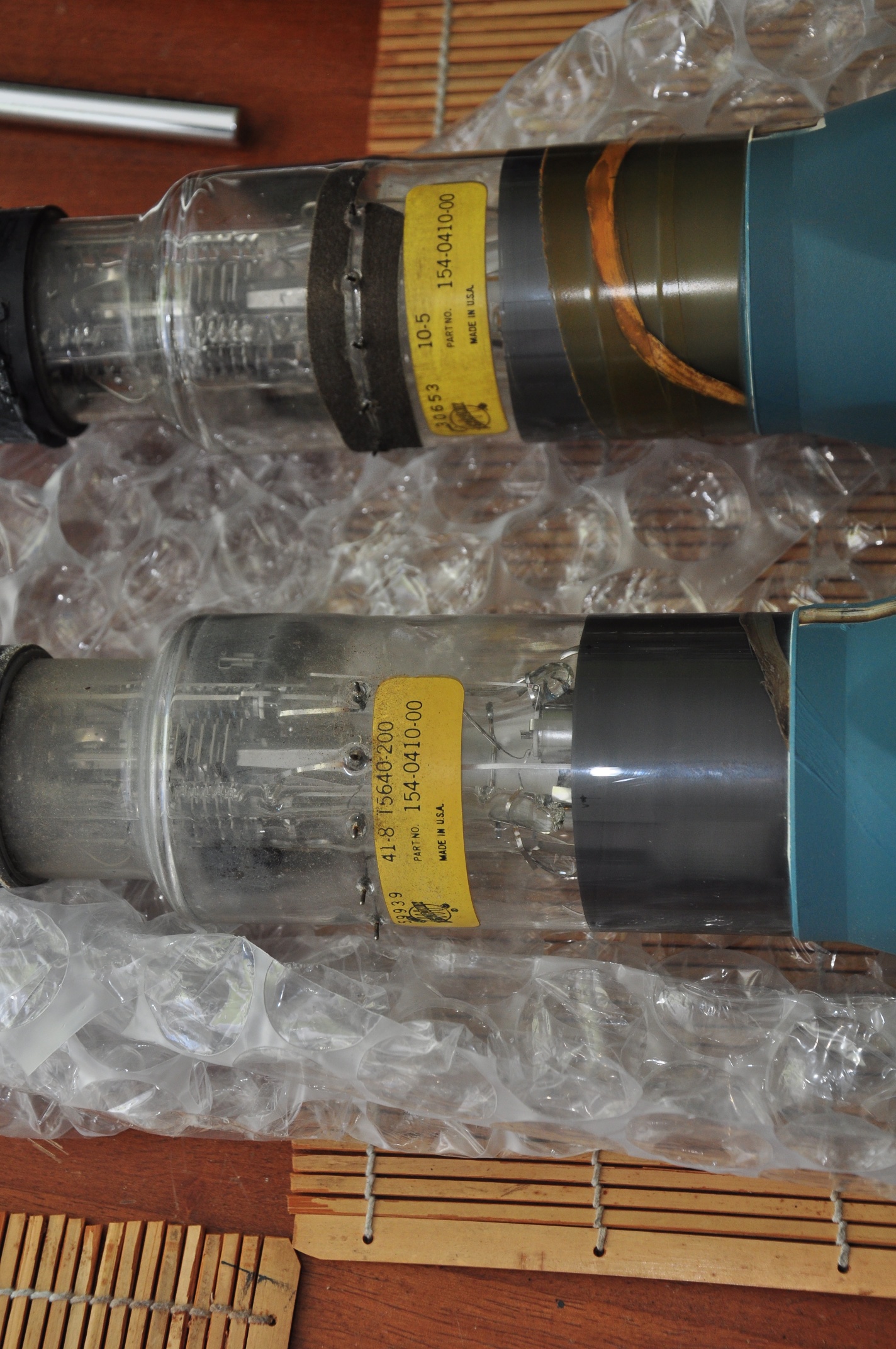
OK though, same part number, we should be good, right? Hmm.. one of these things is not like the other: 
There are 6 pads around the old CRT, and 6 corresponding contacts on the scope. The new screen is missing the 2nd (or 5th?) pad. Additionally, it looks like there’s a conductive trace coming out of the left of the 2nd pad on the old CRT that’s attached to the 3rd trace on the new one. I needed to do a little more investigation before I was comfortable just shoving in the new screen and hoping for the best.
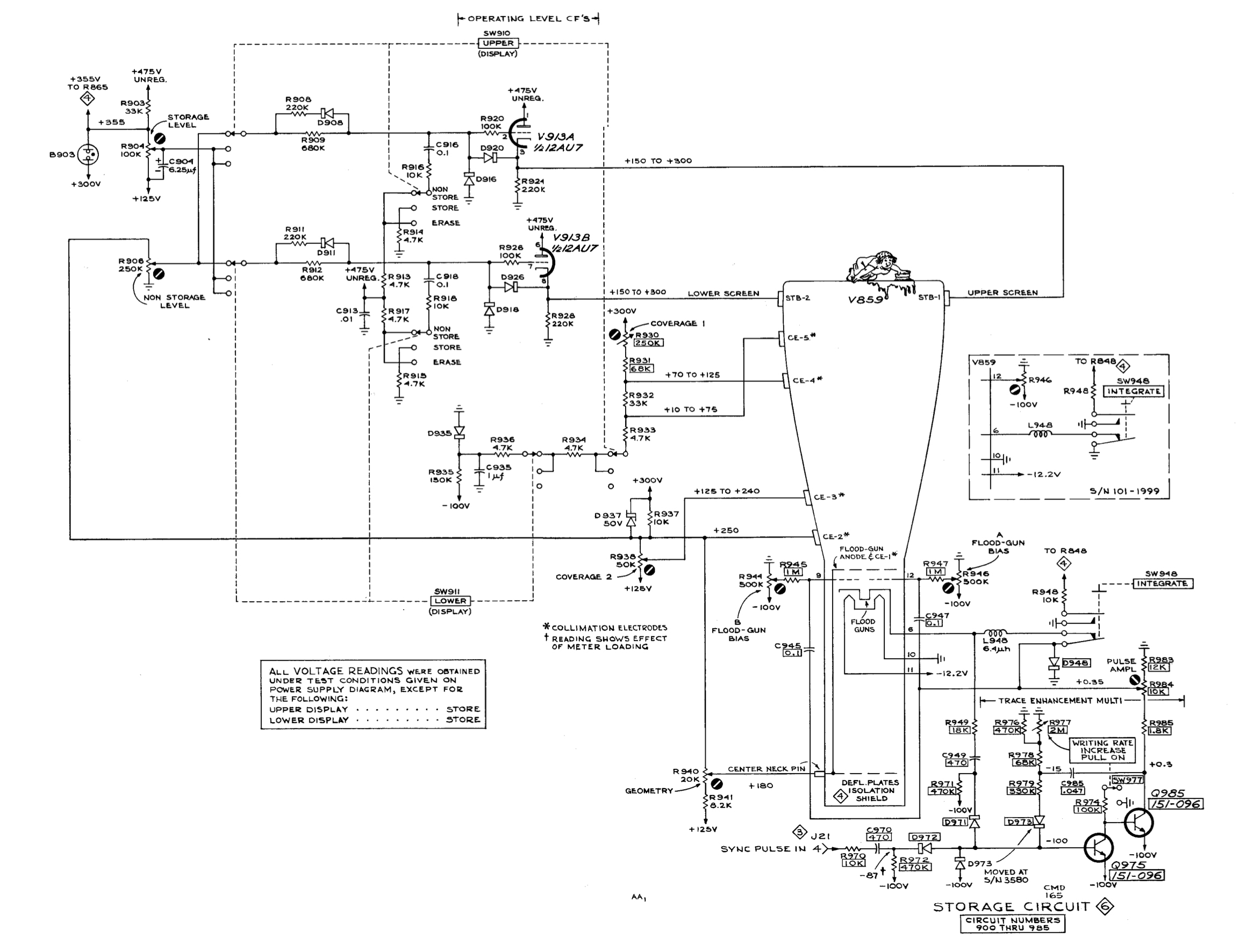
These connections are all a part of the storage circuitry, as seen in the schematic below.
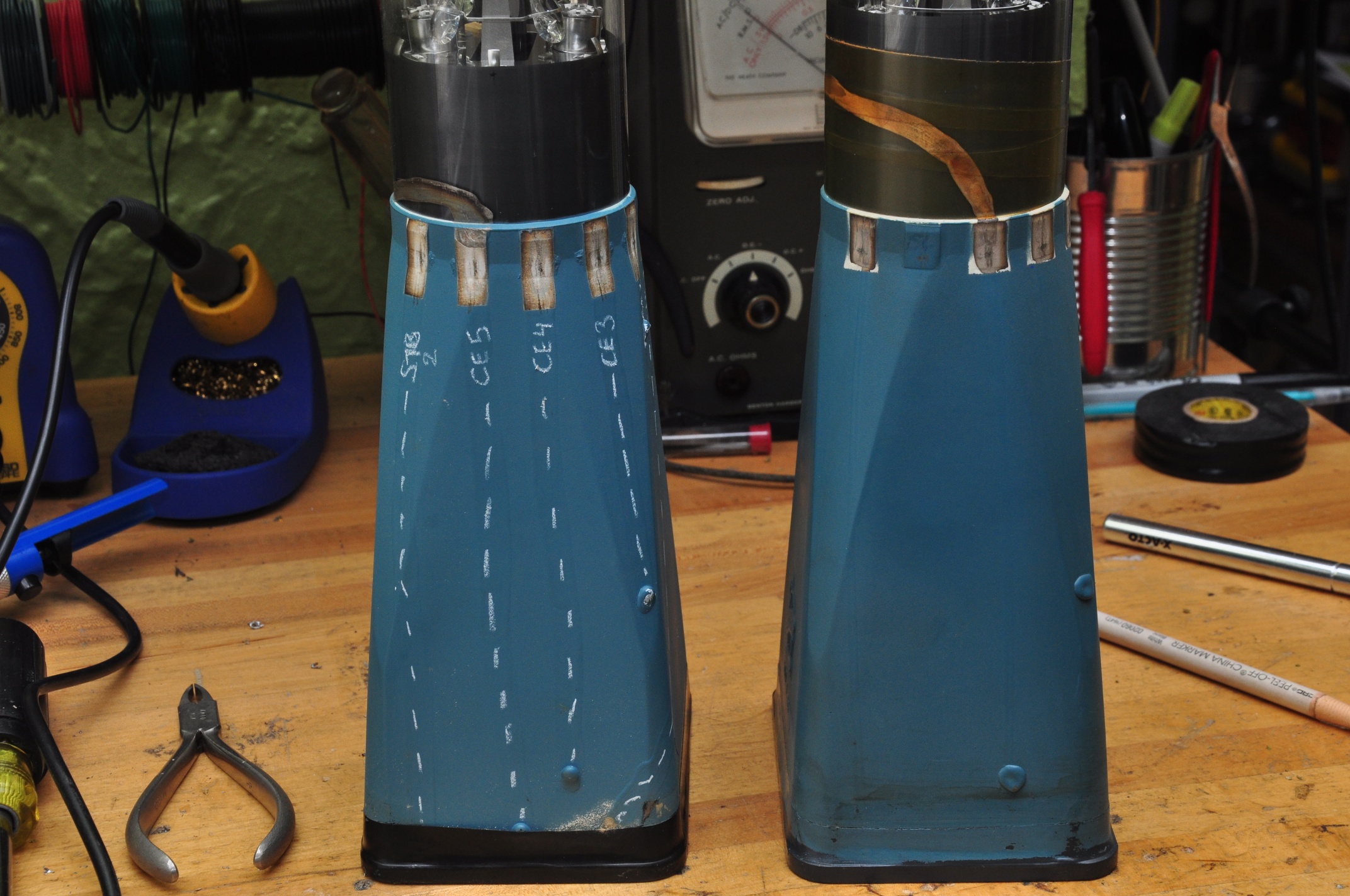
After a bit of cold metering in the scope, I was able to determine which connections were which on the CRT, and I marked them with a grease pencil:

So pins 1 & 6 (counting counterclockwise from the bottom in the scope) are STR1 & STR2, the upper and lower storage targets, while 2 – 5 are CE1 – CE5, the collimation electrodes. I’ve marked the path of the conductive traces so they’re more visible, you can see that they each terminate at the connection to their respective grids.
So the new replacement is just missing the last collimation electrode. That doesn’t seem like such a big deal. Maybe they realized it just wasn’t needed it in subsequent revisions? The original has the ‘T5640-200’ in it’s markings, which matches the description in the manual from BAMA (©1964), but the replacement does not. The replacement has what appears to be a lower serial number, but I’d be surprised if it was the older one; It seems more likely that they removed an electrode in later models than leaving the space and adding one later. Build techniques also differ. The traces and connections on the replacement are finer and cleaner, but I don’t know if that equates to a earlier, smaller, more hand-built batch, or a later, more refined manufacturing process. Any insight would be greatly appreciated.
Feeling confident enough, I carefully installed the new CRT and brought it up slowly on the variac. I got a beautifully sharp trace that didn’t flinch, even with gentle taps on the tube:

As you can see, intensified mode works great.
One of my other recent purchases was a Heathkit TT-1 Tube tester. I started out the previous version diagnosing a smoking resistor in the storage section power supply. Now I had a way to check the tube. Both sides of the 12AT7 checked out OK on mutual conductance and shorts, but one side failed the grid current test (exhibiting lots of it). AH HA!!
I suspect the grid current was causing excessive draw on the 475v supply, which is why the resistor was overheating. I replaced the tube and slowly brought it up on the variac – low and behold the resistor remained cool.
Wait a minute, a 12AT7? The schematic (and nicely silkscreened chassis) calls for a 12AU7. Huh, I didn’t realize that upon first inspection. The 12AT7 has a much higher gain then the 12AU7, and I wonder if that led to the premature failure of the tube. It now has the correct tube.
Next on the hitlist:
- Documenting the storage functionality. It sort of works, but needs some attention
- Understanding the grid current test on the TT-1
- Sourcing a replacement handle. I actually don’t mind going off-brand here, and would dig a custom replacement as long as it made use of the original mounting hardware.
Thanks for the write up. I recently aquired the same scope. Was told magic smoke was released. All looks good except for the intensity/ power on switch. I don’t have any prints outside of your crt scheme. Do you have any other prints to this thing you would be nice enough to email?
Thanks Micheal from Michigan
Hi Michael –
Do you have access to the manual? Kurt’s wiki has links to them here:
http://w140.com/tekwiki/wiki/564
Do you have a 564 or a 564B? The power supplies are different. If you can see damage, then that’s a good place to start. If not, I’d bring it slowly up on a Variac, without plug-ins, and measure all of the voltage rails. That’ll give you some clues as to where to start troubleshooting.
Cheers,
Paul