
I took the red pill. 

Behold the Tektronix 7D01, first released in 1977, shown here with it’s companion display formatter. As a side note, I really need a better lens. This pin-cushioning is just too much. 105mm or 200mm prime macro (or micro as Nikon calls them) is high on the list.
This wasn’t Tektronix’s first bench-top logic device, but it was the first to have a tiny bit of smarts to it.
- In 1975 they released the 821 4 bit word recognizer released in 1975. Yep, a 4 whole bits.
- In 1976 they released the LA501 as a part of the TM500 series instruments. It could store up to 16 channels x 256 bits, and relied on an external display. No word recognizer, no cursor, no read-out, just a simple timing diagram.
Hewlett Packard had a jump on the bench-top logic analysis tools, starting in 1973 with the 5000A logic state analyzer. It’s no WOPR, but a respectable display of blinking lights nonetheless.

By 1975, they had released several bench-top products. The HP Memory project has a great page on the topic.
Back to the 7D01. I’d picked it up a few months ago, and separately picked up one of the two 8 channel probes. The probe connections are to the left of the word recognizer. Note most logic analyzers are useless without their probes, and the probes are usually specific to one product or product family. You can pick up this and other 80’s era logic gear for under $100, but be prepared to spend a comparable amount on a set of probes.
So I started mucking about with it, generating test sequences from an Arduino and learning out how to operate the thing, and saw a variety of intermittent failures:
Here’s the character generator on the display formatter losing it’s mind:

Some extreme jitter in the display of the timing diagram:

Here’s a quick video of one failure mode, this time with the display formatter removed. Notice the characters look different, more on this later.
And here’s one more of the display formatter losing it’s mind in state table mode, filling every unused character slot with a ‘1’.

The thing is, I am now in possession of no less then three of these units, as I was given two ‘for parts’ when I picked up the 7603 & 7D20 a few weeks back. And of course, these units both worked flawlessly. I contemplated just calling my original unit the ‘parts’ spare, but that seemed like a cop-out, so I went forward attempting to repair my original, knowing I had an ample supply of parts, should they be needed. Besides, that’s the real fun anyway.
I studied the manual during my daily subway commute the week prior to attempting to diagnose and repair. Putting the display formatter issues aside, I suspected the counter on the cursor board was responsible for the racing numbers in the video, and that something was wonky with the flag signal which could explain the display blanking.
When confronted with a multitude of seemingly unpredictable problems such as these, the best approach is often ‘take it apart and put it back together’, making sure to take pictures along the way to help in the reassembling effort. This isn’t just the physical equivalent of ‘have you tried turning it on and off again?’; Close visual inspection can reveal failed components, and re-seating 35+ year old connections can often fix intermittent problems. Besides, without plug-in extenders which would let me probe around on the live-plugin running outside the mainframe, there really wasn’t much else I could do.
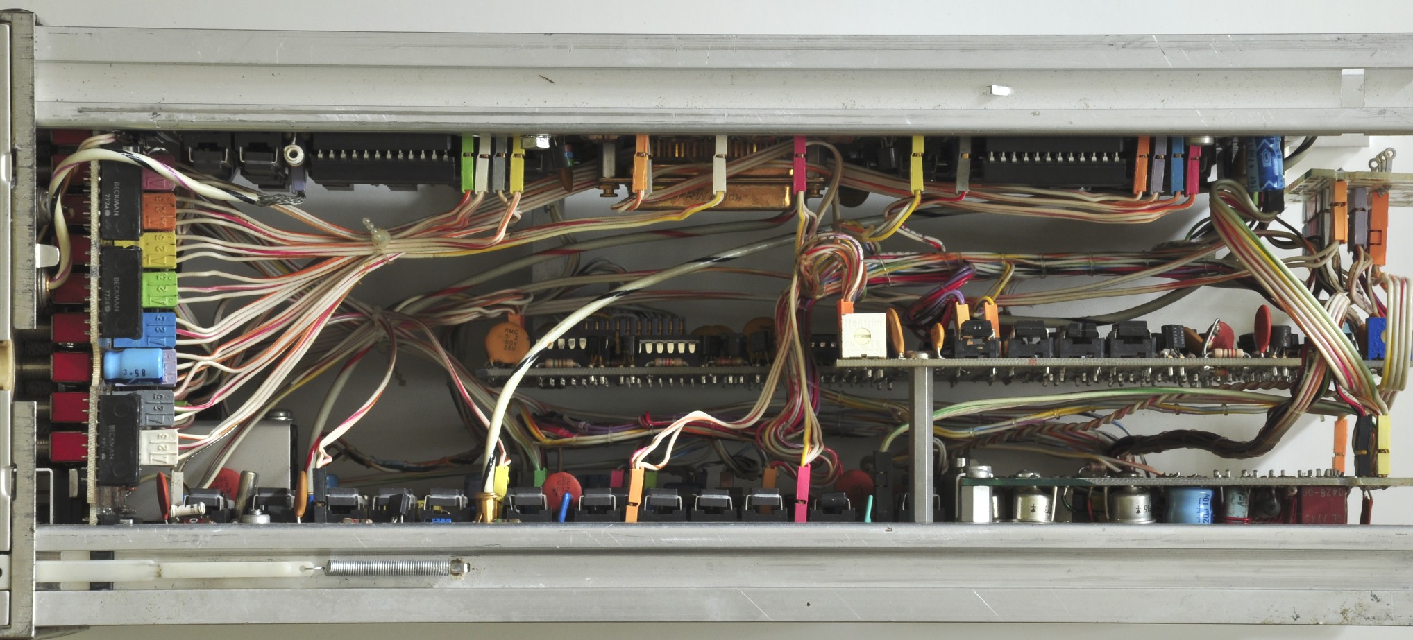
Left Side w/ Display Formatter removed. The D-sub connector toward the back is where the Display Formatter connects. 
Right Side, showing the two delay lines:

Top View, after removing the back plate:
The rear with the backplate off, before any further disassembly. 
Removal of the edge connector card: 
The card removed, shown from the other side:

Disassembly continues:

Cursor board removed:

The same board backlit:

Memory board removed. Tremble in awe at 512 BYTES of Static RAM. (arranged as 16x 256 bit chips).

Dear god what have I done:

As you can see, it wasn’t a total teardown. I left the output board and word recognizer in place, as I could now reach and re-seat all of their connections and chips.
I didn’t individually pull and re-seat every chip, but I did give them all a firm press, and found that many had worked themselves loose. All that SRAM and discrete logic really cooks, so it’s not surprising to see failure modes change as the unit warms up and pins move slightly as they heat up and expand.
It took another hour or two to get the whole thing back together. While I took a bunch of photos (more then shown here), I still had a few stray wires that I needed to hunt down in the manual to figure out where they reconnected. It helps that the wire harnesses are pre-bent and just the right length, so often times it’s obvious where to connect; however that also means there’s little to no slack, so there’s really only one way to route each wire. I had a few runs that I had to re-snake through after I realized I’d taken the wrong path.
After one more visual check, I slid the plugin back into the 7603 mainframe, held my breath, and pulled the power button (it’s a strange power button).
WHEW. Works like a charm.
Here it is a little while later, after I reattached the Display Formatter (DF01).

Notice the difference in how the characters are drawn. The details of both are worthy of their own posts, but short answer:
The mainframe’s built-in character generator uses a column & row format to address each character, but the characters themselves are drawn as a series of vectors.
The character generator in the DF01 (and DF02, and 7D20) addresses each whole row of characters as a scanned, raster canvas. Interestingly, when a ‘pixel’ in a character is to be drawn, not only does it unblank the beam, but it also makes the horizontal scan pause for a moment to attain sufficient brightness on that spot.
In the above image, the top and bottom rows are handled as a raster canvas by the DF01, while the timing diagram is swept in the traditional method; one horizontal sweep for each channel. The DF01 & 7D01 are each responsible for their own portion of the canvas. In either case, the 7D01 handles all of the X, Y & Z signals to the mainframe; there is no direct connection from the DF01.
Here’s the state table view in compare mode. It’s comparing the acquisition to empty memory. Any bits that are different are highlighted (in this case, all of the ones).

Note that in this mode, the everything on the display is being generated as a raster from the DF01.
This is most awesome – and I really like the title of your blog page!
Hi Paul, A kindred spirit! Beautifully written and documented. Obviously a labor of love. I have three 7D01s, the 7D01, 7D02, and the DL2. I bought my first 7D01 new in 1978 for $3,000 (YIKES!). The other two I got on Ebay more recently for 1/60th of that price. Over the years they seem to have stopped working reliably. I discovered an interesting Tek Engineering Note that probably went out to all the field offices in the late 1970s to warn them that the sockets Tek used at that time were not as reliable as the manufacturer had originally indicated. As you know the 7D01 has ALOT of ICs on sockets. What I discovered was that pushing down each IC snugly once in a while would fix almost all of the reliability problems I was seeing.
Dennis Tillman W7PF
Hi Dennis – Thanks for reading, and for the kind words! Ah right, you’re the one with the (seemingly only!) 7D02. Have you posted any notes, photos or videos of it? All of us on the tekScopes board would love to see it in action!
Great post on the mixed domain functionality, btw. I finally got the readout on my 7834 working 100%, and experimenting with that feature is on my short-list.
thanks,
Paul
Pingback: Heathkit H89A – Continued boot failures | Buttons, Switches, Knobs & Lights
Paul,
Thank you for posting your experience with the 7D01. I have two of them – a “good” one and the other one. The good one worked perfectly some years ago when I last used it. The other one acted like what you describe in this blog. After reading your blog, I’m thinking of plugging them back in my 7704A scope and see what happens.
Thanks,
Jim