
I picked this up at a HOSARC Hamfest two or three years ago for $20. The guy said it mostly worked, and it indeed mostly did. 
I had never heard of this company before, and searches on the internet don’t unearth too much detail.
The unit works fine up to the 3rd range setting, but the ‘X1KC’ & ‘X1MC’ ranges were temperamental to say the least.
Time to crack ‘er open:

A very compact design for the era.
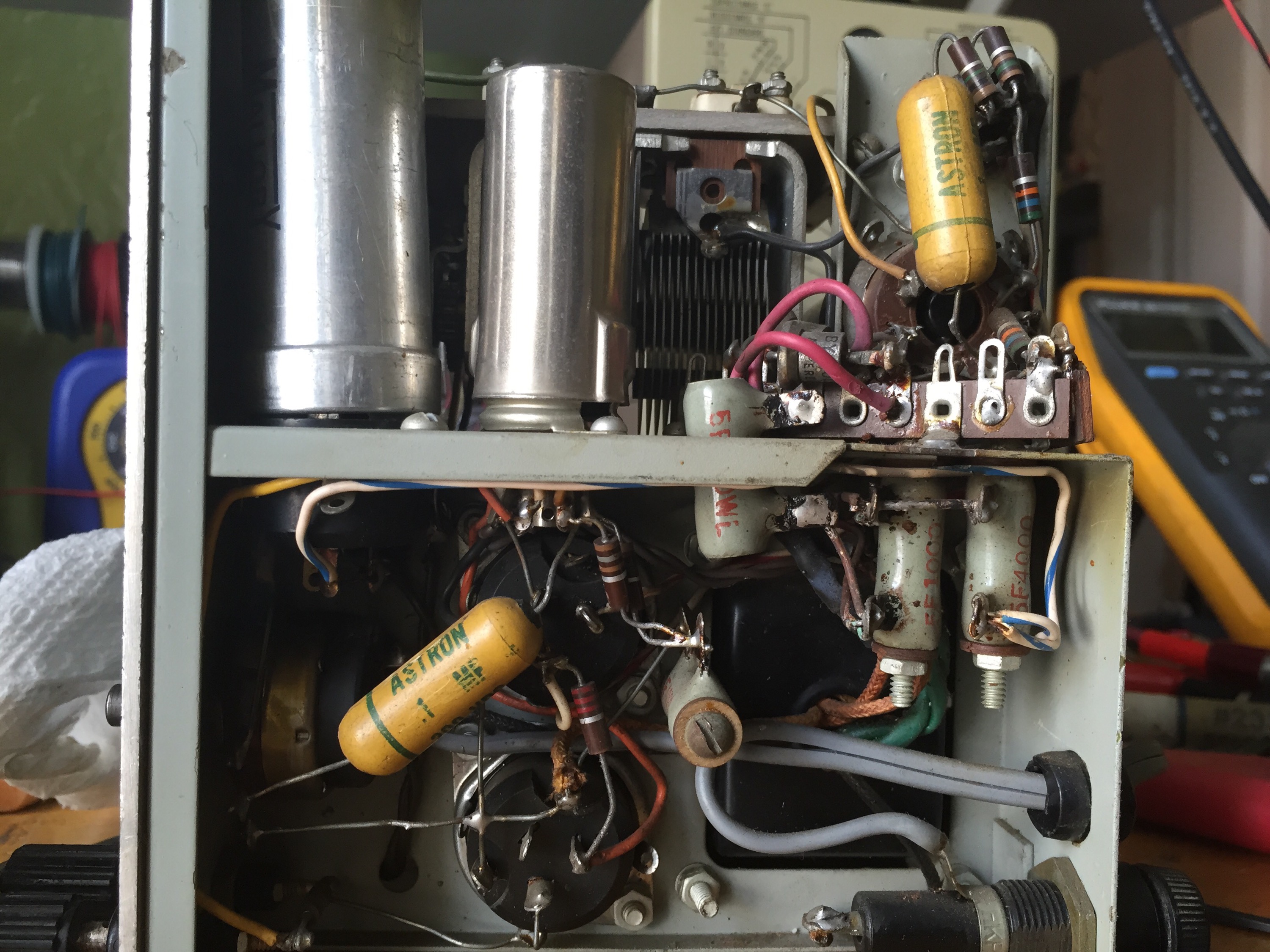
major components:
(2) 6AK6
(1) SJ7
(3) dual 20uf @ 350 cans.
(2) diodes in the power supply (non-regulated)
(1) ballast lamp
It appears to be an RC Wien bridge oscillator, with precision resistors on the decade switch, and a dual bank variable capacitor for the frequency knob. Also typical of the era is the incandescent lamp as a part of the oscillator feedback circuit. Basically, the gain of an oscillator must be exactly one to sustain oscillation, but in order to initially achieve it, a gain of more than one is required. The incandescent lamp’s resistance increases as it heats up, so when used in the feedback circuit, the gain can start high, then level off at 1 as the lamp warms up. Good explanation here.
Here’s the output level control / power switch
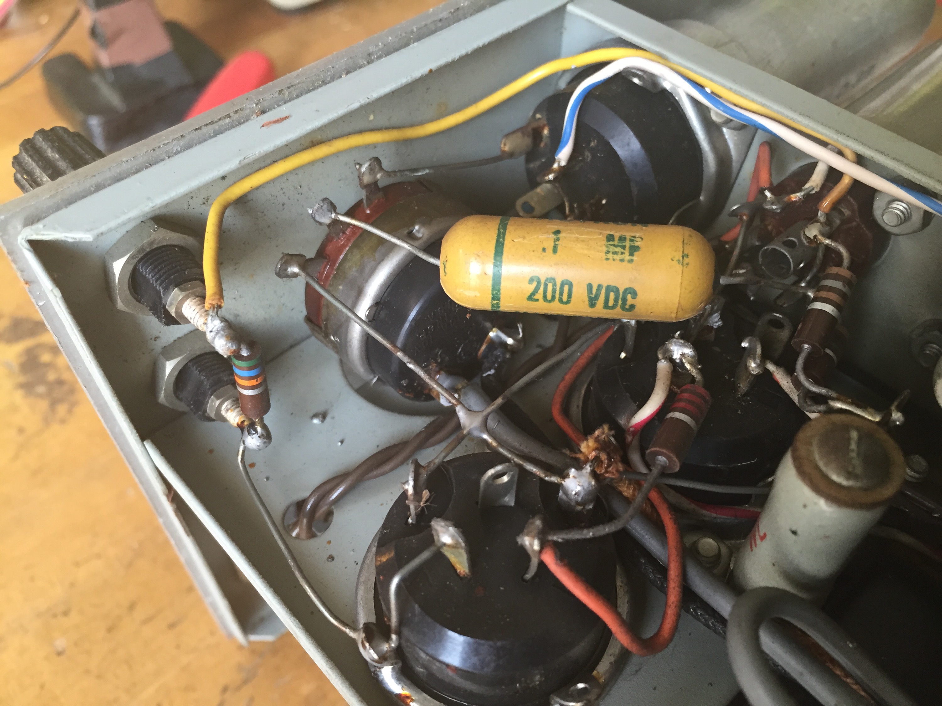
I yanked the knobs for cleaning
Tubes were tested

It starts to clean up nicely

Tube shields cleaned with damp aluminum foil, acrylic pointer cleaned with detergent, and took the surface rust off the screw heads with a wire brush.

As far as the last two bands, a thorough cleaning of the switch greatly improved the situation, though the highest scale still sometimes needs a little wiggle. I suppose I could entirely remove the switch and give it a real cleaning…
It cleaned up OK:

Here’s the output through my Heathkit HD-1 Harmonic distortion meter. Channel one (on top) is the signal from the oscillator, Channel 2 is the output from the distortion meter. This output is the difference between the original signal, and everything except an ideal version of the original signal; a better & more detailed explanation here (same site as the previous link – good resource!)
My dumbed down version – this output shows where, in which direction, and by how much, the signal is incorrect; it basically points out where your waveform sucks. An ideal sinewave would show as a straight line on the output of a properly tuned HD-1. 
In contrast, here’s the same setup with my Heathkit AG-9
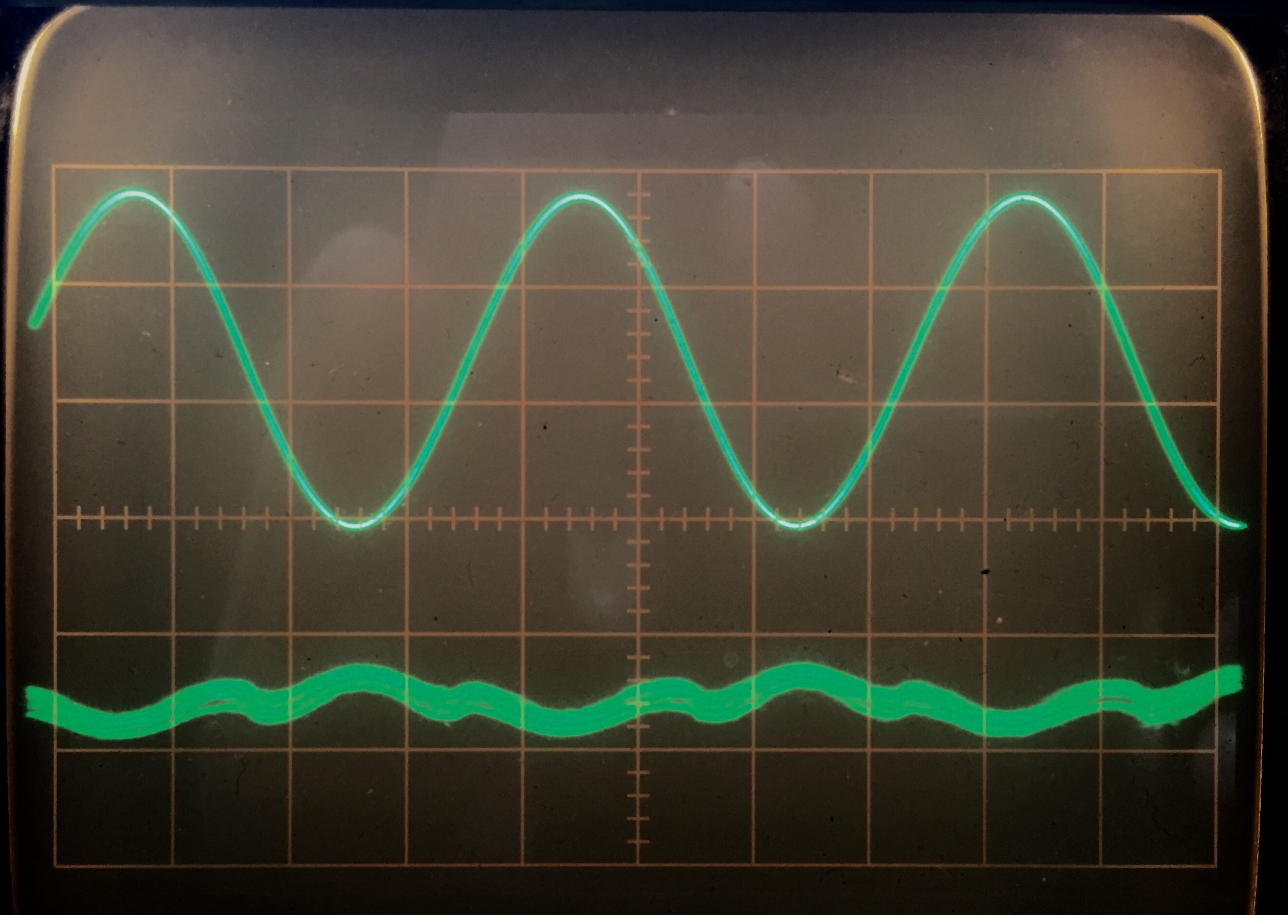
though timebase is different, the amplitude ratio is the same; the AG-9 blows this Oscillator out of the water.
Manual en route, stay tuned for more.
UPDATE 8/4:
Manual posted here
Pingback: Tektronix 620 XY monitor repair | Buttons, Switches, Knobs & Lights