Heathkit H89A – floppy config & attempted boot

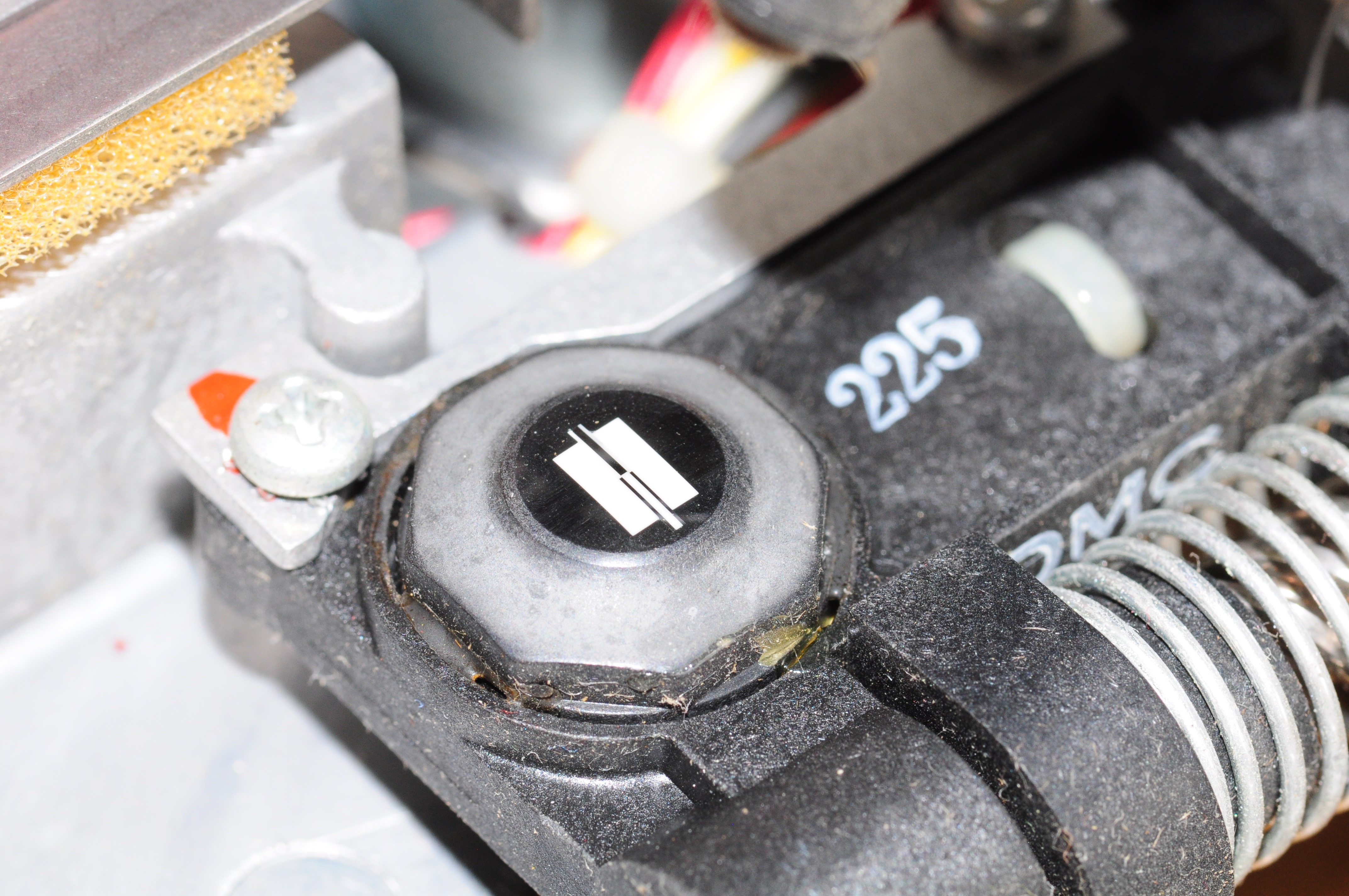
I’ve tried every disk in every drive with what I thought was the working configuration, to no avail.  Every failure is the same: hitting ‘b’ to boot, getting ~5 seconds of disk activity, and failing with ‘? Boot Error’.  Heads appear to be in impeccable condition, and the disks look clean.  Here’s a closeup of the heads on the hard sector drive:

Floppy drive head closeup

And here’s the collection of disks I’m working with:

img_6437 img_6439

SW501,4 controls which card to boot from:
0 = H88-1 Card at P506/P512 (the right most slot), I/O Port 174
1 = Z89-37 Card at P504/P510 (the left slot of the right bank, I/O Port 170

I’ve tried both; 0 boots to the internal, hard sector disk, 1 boots to the 1st drive in the H-37 enclosure, a 96tpi soft sector drive.

The internal drive is set to Unit Zero (or DS1) for use with the H88-1 card
Screen Shot 2016-08-14 at 3.45.36 PM

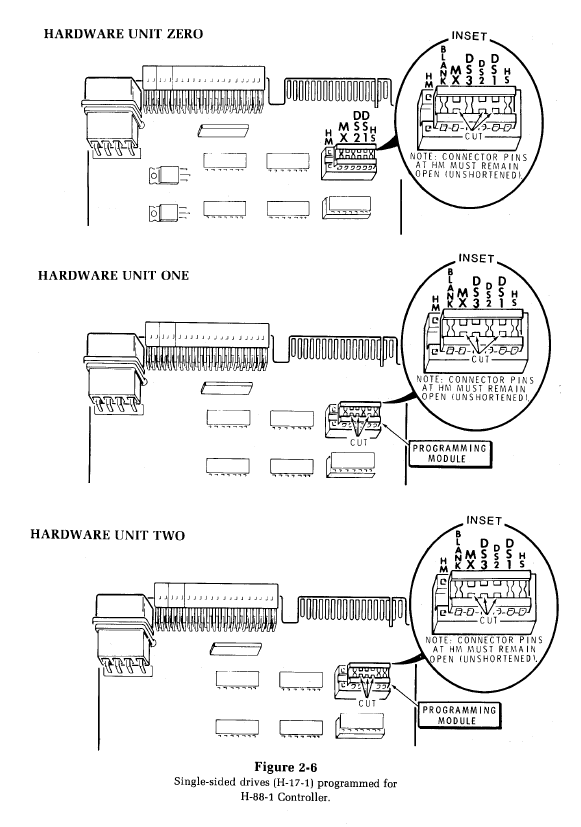
But wait, we can also use this drive as a soft-sector drive on the the Z89-37 controller.  Note that the drive settings are different:
Screen Shot 2016-08-14 at 3.45.44 PM

Yes, it’s backwards.  My predecessor was nice enough to not cut the links, but to simply bend the pins of the package out.  unfortunately, they’re super fragile, and a single attempted bend broke the pin, several times. I ended up using a portion of the original package and some wire.

Note that J4-J7 needs to be set correctly on the Z89-37 card.  It’s now set to J4, meaning the single drive ID’s as DS1 plugged into P3 (the top port on the card) is Drive 0.

As I was shuffling connectors and moving the board around, this happened (took me a few minutes of failed boots to spot):
img_6436

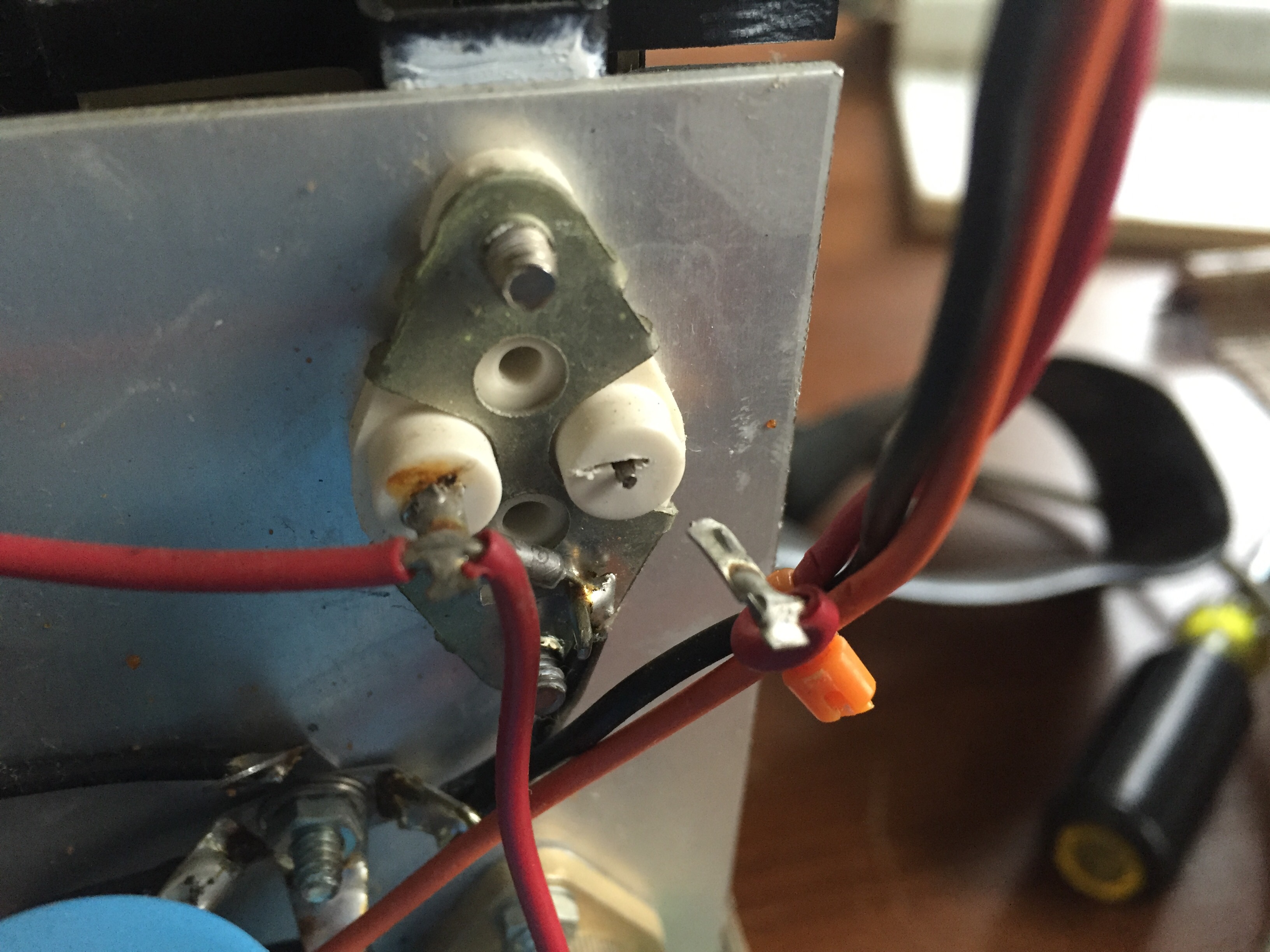
I temporarily crammed it back in, and got to the H: prompt.  Still won’t boot to a disk.

I wonder if this is noteworthy:
Every boot attempt seemed to take the same amount of time to fail (3-4 seconds), regardless of which configuration or even if a disk was present.  When I jump J4 on the Z89-37 (what I believe to be the correct config), an attempted boot without a disk tries indefinitely and never fails.


Heathkit H89A, First Light

Progress continues.  I tested the regulators and they were fine.  I ultimately traced the problem to C513.  It was shorted, and has been replaced by a comparable ceramic cap.

After bringing her up on a variac, I’m greeted with an H: prompt!

I ran a memory test, which is one of the routines in the monitor ROM.  A full test would take over 2 days, so I just let it run for a bit after quitting.

IMG_6407

377377 is 64K in octal.

There’s a routine you can enter manually that prints characters to the screen:

IMG_6410

Finally, there’s a routine to run a drive speed test.  Using a tweaker to adjust to 200:

IMG_6424

Unfortunately, I can’t get it to boot off any medium I have, either hard sectored on the built-in drive, or soft sectored using the external H77 drive.  Not sure what to try next…

IMG_6423

Heathkit H89A computer, first repair attempts

I’m just jumping right in –

I acquired the following from Ray (WA1FFT) in NJ.
  • Heathkit 89A
  • Complete set of spare boards from H89A (different mb)
  • H17 Dual hard sectored 5 1/4” floppy drive
  • H77 Dual soft sectored 5 1/4” floppy drive
  • Box of hard & soft sectored disks.
I was really just after the H17 to go along with my H8, but $30 for all that? No brainer.
Ray warned me that two caps popped on the main board,  and indeed C508 & C515, 2.2u tantalum caps, failed violently.  We’ve got to see what other damage they did; tantalum capacitors are like the suicide bombers of the electronics world.
IMG_6388
They were replaced with 10u caps I had in inventory (close enough):
IMG_6394
I found Herb Johnson’s 2016 adventures in Heathkit H89 rebuilding while surfing around, and his page is a great reference.  As I got a spare set of boards as well, I figured I’d first just swap them out.  No go.  The boards are slightly different, and that difference includes the power supply connectors.  According to Lee Hart, the key’d power supply molex connector indicates a late-model H89A.  That would be the 2549 board
I’m assuming that also took out U585, a 79M12 and U565, (only have a heath part), as there’s no -12V & +12V on the output of those regulators.  I also have a spare, earlier model board to compare with (and possibly steal parts from if I’m impatient), but I’m noticing more and more inconsistencies between the two boards, and with the documentation.  Here’s where it gets (more) annoying:
U515 is a 71M12C, your run-of-the-mill -12V regulator.  OK, terrific.  Same on the old board as well, and consistent in all docs I have.
U567 only has a heath part#, 442-674.  It’s in parallel with U568, they both feed separate +12V supplies.  Here’s where it gets squirrelly:
  • In the docs, it’s called out as part 442-663
  • The pinout labeling is different (common pin center, whereas board image & earlier board call common pin as the left one)

Here’s the old board (85-2208-1) incorrectly marked pin-outs, but check out that sexy ceramic ram chip:
FullSizeRender(2)

Here’s the documentation for the newer board, but the pin-outs are still mis-marked:
FullSizeRender

Here’s what I’m left to deduce, and can confirm after some metering:
  • The earlier board silkscreen and artwork in my manual (for the later board) are both wrong for U567 & U568
  • U515, a negative regulator, indeed has it’s common (gnd) on the left; it’s input and output are swapped from positive regulators.
  • U567 & U568 are almost certainly 7812s (+12V regulators), as they are on the earlier board.  They are only silkscreened correctly on my newer board.  The new board artwork illustration, and the old board silkscreen are both incorrect.
GRRR….
OK, well U515 seems to be working well out-of-circuit, but there’s almost no resistance between ground and it’s output in the circuit.  Suspecting C509 & 511 next.  Lifted both, no dice. I’ve got to be careful with the desoldering gun, the traces are easy to lift.
So what else is connected to the -12V line?  Besides the 2 -5V regulators, and the card bus, I’d imagine it’d be the built-in UART used to communicate with the terminal board, since for whatever reason, it’s full blown RS-232 between the two.  Yep, sure enough there’s a quad EIA-232 driver. Nope, there’s still a short with that removed.
So it’s the -5V regulators?  Nope.  Forgot about C513.  Yep, it’s shorted.  It’s always the last place you look…
Next up – replace the regulators and attempt to power up again.

Summer 2016 check-in

I’m just surfacing for a moment because I realize it’s been over 3 months without a post, which is just plain unacceptable.

HOPE XI just wrapped up, and I was there for at least a part of each of the three days – never really staying for the late stuff, but managed to catch at least 4 – 6 talks per day.  The highlight was (as it was two years ago) Deviant Ollan & Howard Payne’s tag-team talk.  This year was about the often abysmal state of physical security, manifested through commonly keyed locks.  Their last HOPE talk was on Elevator Hacking, and the subject of keys was one of it’s focal-points.  I highly recommend checking out the Elevator talk on YouTube.

Other highlights this year included:

I’ve started playing around with Collective Access – an open-source Collection Management System geared towards museums, libraries, and other archival institutions.  I found it after searching in vain for a WordPress solution for digitally curating the collection I present here.  I’ve got about a dozen objects added so far as I learn how it works and tailor it to my needs.  There is an underlying structure that makes it well suited for museum collections, but it’s highly configurable through the web interface;  Vocabulary, relationships, meta-data, object hierarchies, and user-interfaces can be customized without touching a line of code.
It’ll be a few more weeks until I’m comfortable enough with my schema, and I may start to post about my progress.

While at HOPE, I caught up with Evan of the Mid Atlantic Chapter of the Vintage Computer Federation, who (among other things) gave an interesting talk on his work researching early computers.  I’ve got the beginnings of an idea to use Collective Access to help them catalog their impressive inventory.  There are some real gems there, and beyond just cataloging, I’d love an opportunity to take some glamor shots.

The 514 is slowly coming to life – The +225v supply isn’t regulating to full voltage, and I’ve narrowed the problem down to something on the upper deck (the input, vertical amplifier, and calibrator).  With that disconnected, I get a nice, sharp, swept trace.

swept trace w/ upper deck disconnected

swept trace w/ upper deck disconnected

Sorry for the extended black-out, more to come!

Tektronix TM-503 repair

The third bay of my recently acquired TM-503 mainframe ate two plug-ins, releasing their magic smoke.  The it didn’t do this to the module that came originally installed in the 3rd bay, and here’s why:

The mainframe has two power transistors for each bay that are wired to the edge connectors.  They’re meant to be used by the plugin’s power supply.  The DM-502 that was originally in the 3rd bay didn’t actually use these transistors, but the DC504 and FG501 did.  The photo below shows 3 of these transistors.  The one on the far right is for the center bay, and it has a mica disc insulating it from the chassis.  The two on the left did not have those mica insulators.  Some knucklehead that replaced the left-most transistor (center one removed by me), forgot to re-install the mica disc, and I found one floating around the inside when I opened it up.  This meant that one of the pins was shorting to ground, and he was only lucky not to get bit because of the plug-in he was using.

You’ll also see a 5v regulator bodged onto the unit, it’s output has been snipped.

IMG_5775.JPG

Here’s the damage caused by the error:

A blown trace on the DC504IMG_5776.JPG

And one of two blown resistors on the FG501.  I’ll have to order replacements, they’re .27Ω, of some reasonable wattage.  IMG_5777.JPG

The trace repaired:
IMG_5781.JPG

And the mica replaced:
IMG_5780.JPG

DC504 is back to life. It’s not the greatest counter, but it claims it’ll go up to 80Mhz.
IMG_5782.JPG

Viking Valiant – How to pack a classic beast for shipment

The basement clean-out continues, and today I bid farewell to a Viking Valiant, a 160M – 10M AM transmitter good for 200ish Watts.  It’s big, heavy, and full of tubes.  I picked it up at a ham-fest over 20 years ago.  It was a fixer-upper then, and nothing has changed.  The face-panels is a little rough around the edges, but the logo, meter, knobs, and most of the markings are intact.  The coils, tubes, and variable-capacitors are in good shape, and there aren’t any signs of oozing goo from any of the transformers.  This baby is ripe for a restoration, and it’s about to get it’s chance.   DSC_0750

These were available from the mid 50’s through the early 60’s and could be purchased as a kit, or fully assembled.  A very nice gentleman in Texas won this auction, and I do hope he posts some pics & notes of his restoration process.  I can say in my limited dealings with people on eBay that folks who are technically knowledgeable and really understand what they’re buying are generally a joy to deal with.  I stipulated that anyone contact me before bidding so we could discuss the shipping logistics, which I think helps ensure a smoother sale for items like this.  Someone contacted me and asked if the transmitter supported SSB; I’m glad he didn’t bid.

What follows are the pics I took for the eBay sale, as well as pics I took while packing, to give an idea of what’s involved in packing an 80 pound transmitter full of rare vacuum tubes.

DSC_0754 DSC_0755 DSC_0757 DSC_0758 DSC_0759

DSC_0760

DSC_0762

High power RF is a beautiful, black art to me.  DSC_0763 DSC_0765 DSC_0768 DSC_0769

This  mechanism is kind of cool: at certain points in the front panel knob’s rotation, the pins in attached plate mate with an angled groove in the block attached to perpendicularly mounted rotary switch.  DSC_0770 DSC_0771

First, take out all the tubes and individually wrap each one in bubble-wrap.  I didn’t mark the location of individual tubes – he’s doing a full restoration, he can figure it out.  I did however make sure to group the 6146 tubes as they were installed, just in case they were matched somehow.

The tubes get packed in a separate box, lined with bubble-wrap:

IMG_5755.JPG IMG_5756.JPG IMG_5757.JPG IMG_5759.JPG

IMG_5758.JPG

layers of bubble-wrap between each layer of tubes, keeping the tubes away from the edges of the box. IMG_5760.JPG

Then the transmitter gets wrapped:

IMG_5761.JPG

Then boxed:

IMG_5762.JPG

I slipped another box over this (not shown).  In the background:

– Tek Plugins, 1A1 & 1A4
– A  Hickok rip-off of a Tek plug-in (subject of a future post) sitting on top of a…
– Supreme model 589 tube tester (my first tube tester)
– HP 606A .5 – 30MHz oscillator (Free to a good home)
– Eico tube-tester, hitting eBay tomorrow (my… 3rd tube tester?)
– HP Counter, which I’m totally keeping
– My very first ‘scope, the venerable Tektronix 545A

IMG_5763.JPG

Then brought to the packing store where they put it in another box, with a rigid foam base, and surrounded by peanuts.  The resulting box is gigantic, heavy, and unwieldily…but safe.  There’s at least 2 layers of cardboard and 6″ of packing between the transmitter and the outside world.

IMG_5769.JPG

I used about 200 feet in bubble-wrap when all was said and done, plus god knows how many gallons of peanuts in the double-boxing.  It cost $190 to get both boxes from NY to TX, including the $25 he charged me for the double-box.  This is a close approximation of what you may go through to ship an old Tek 500 series scope, although I don’t know if I’d feel the need to pull the tubes.. maybe just the bigger ones.  In retrospect, I probably could have just left the 7 pin & 9-pin miniature tubes in place.

Fingers crossed for a safe voyage!


Don’t desolider angry

desoldering DIPs with an iron, wick, and a sucker is about the most annoying thing a man can do with his precious time on this earth.  The frustration has probably chipped away days off my life, so there’s now a Hakko FR300 de-soldering iron on its way to me.

RIP DC508A, you never really had a chance.

On the plus side, there’s now one more working DC508A display available.

Tektronix 514: restoration update

A bag of parts from Newark arrived and I went to work replacing capacitors in the power supply.  First, I finished re-stuffing one of the cans:
IMG_5582.JPG IMG_5585.JPG IMG_5583.JPG IMG_5584.JPG

I’m really happy with how these came out.

Than went to work replacing the old bumblebee caps – here’s a few shots before I soldered and clipped the leads.  C102 is the re-stuffed can freshly installed.

IMG_5587.JPG

IMG_5590.JPG

I was conflicted about just ripping out old components and replacing them with new ones, but (and I’m paraphrasing his words from a conversation I had with Kurt): Tektronix used the best components they had available to them at the time.  If they had these newer, more reliable components, they would have used them instead.  You shouldn’t feel bad as long as the restoration is done in the spirit of the original design and keeps up with their level of craftsmanship.  I’m happy with my work so far and think I’m on the right track.

I decided to power this up on the variac.  It was almost midnight, so I didn’t bother with photos or videos, but:

I started to hear the whine of the high voltage power supply around 60 VAC on the input (frequency is around 4kHZ, wonder if this is right?).  Eventually I saw a fuzzy green dot on the screen around 80VAC, that quickly drifted off.  If I turn the intensity control all the way up, I see the familiar glow of on the screen you get when the beam is deflected way off the face.  All other controls are unresponsive.

The +1,500V supply is around 1,000V, the -1,500V supply is around -800V.  I would like to get those missing 1,200V back…  The -140V supply seems to regulate albeit somewhat loosely.  The 225V, not so much, and the 225V adjust control doesn’t do anything.  I’m suspecting I have to replace the reminder of the .01μF bumblebee caps in the supply.  Maybe I should just rename this hobby “replacing old capacitors”.

It’s a start!

Hickok 156 Traceometer: 5 Minute teardown

Here’s a first look at my Hickok 156.  This was intended to be an ‘all in one’ solution for a radio repairman’s bench of the era, combining both standard and frequency selective voltmeters, as well as a watt-meter, and monitor speaker.
This newsletter has a great article by David Boyle, who restored his own Kickok 156.