Posted on by Paul Carbone -- Last edited on March 13, 2026
I started working on this 10 years ago when I got the $300 monorpice 3D printer that had just come out. It kind of sucked, so I printed a few things then it sat on the shelf before I just gave it away.
Fast forward 10 years and I was given an old Ultimaker 2. It’s finicky, but it mostly works. With my new basement shop space nearing completion, I figured I’d give these another go.
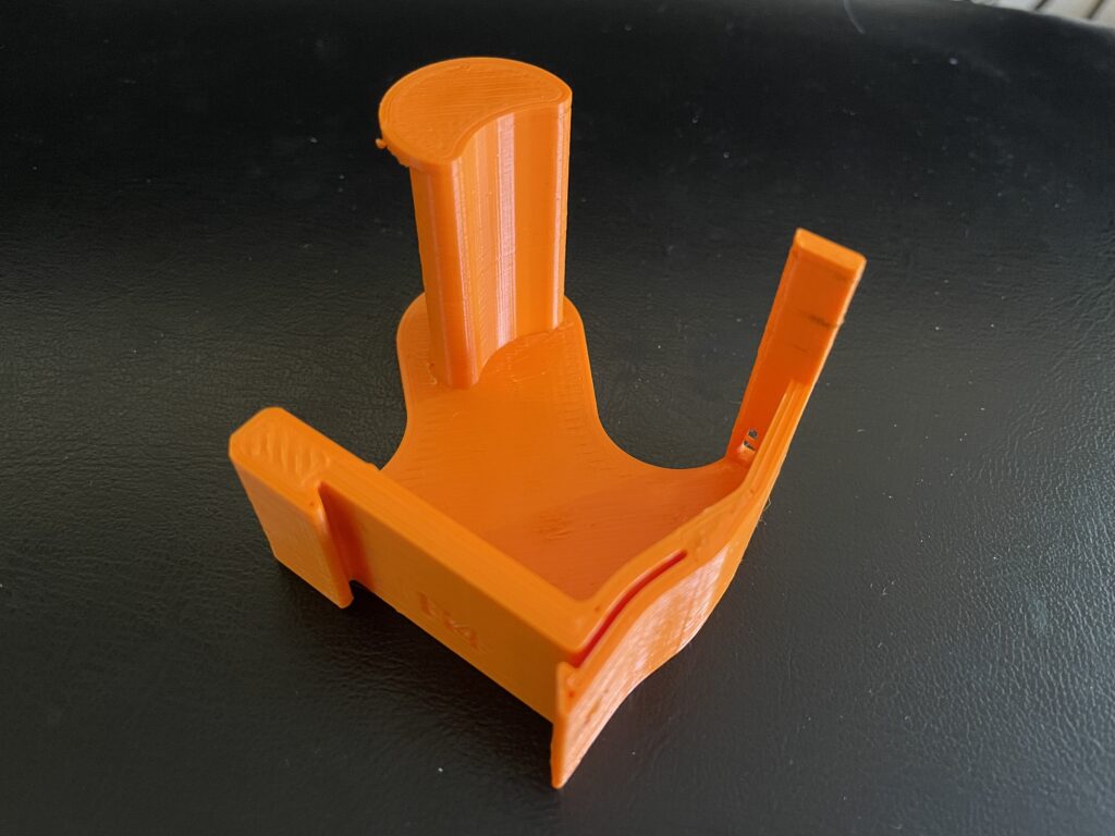
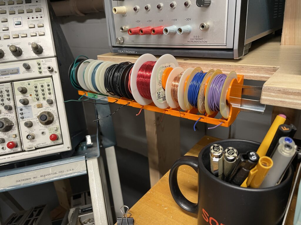
So far I’ve made 2 different sizes – one a ‘standard'(?) for many of the cable spools I have, and a bigger one for a magnet wire spool.
Unfortunately I can’t find the source of the original DIN clip & latch profile to give proper credit, but there appear to be a number of remixes on Thingiverse.
Anyway, here’s the file if it’s useful to anyone, licensed under my ‘Don’t be a cunt’ license, which I’ve yet to write.
Posted on by Paul Carbone -- Last edited on January 3, 2026
Just wanted to get the word out somewhere, since I only found this on a facebook post after a bunch of digging: If you’re trying to update a Yamaha QY100 sequencer to latest firmware found here, you have to use XGWorks, which can be found on this page.
I tried using Sysex Librarian and got a ‘range err’ at line 1177 I tried using Bome SendSX and got a ‘dram c.sum err’ also at line 1177 (Line 1177 is shorter than the others for some reason)
Install XGWorks – seems to install fine on Win10-64
Extract the firmware zipfile and follow the instructions in the readme for putting the sequencer into firmware mode
Launch XGWorks, and open QY100_v137.mid
Make sure the correct midi interface is selected, and press play.
The whole thing takes about 15 – 20 minutes. Initially you’ll see it erase the current firmware, then it’ll say OK for a bit, then it’ll show an Address = xxxxxx that will start counting up. It will periodically stop, say OK, then start counting up again, and eventually you’ll see a message saying it succeeded. If you use any other sysex utility, it will just keep counting up until it throws one of the above errors at line 1177 (the address will vary, but it will always be at that line in the sysex file).
Just in case, here are local links to both resources (I like to link to the original sources whenever possible, but also like to have a back-up) QY-100 Firmware 1.37 XGWorks
Posted on by Paul Carbone -- Last edited on July 5, 2025
Should have started this page a few weesk ago, and taken better notes, but gotta start somewhere.
The Gist: got a plotter; had to replace some rollers; tried with varied success to refill some of the pens; it’s awesome; curves are hard; fonts are harder; workflow needs work.
References (in no particular order):
Comment thread w/ chevycasanova & myself on this instagram post.
This blog post about truetype fonts, and how some of them are secretly multi-line, even when they claim otherwise. They’re also working in Rhino, so that’s a huge plus.
There’s a current, commercial HPGL driver called WinLINE for $190.
A blog post about engraving fonts, with some more info about engraving fonts, as well as some links for single-line fonts, also known as open path fonts.
Ah HA! So, the SLF-RHN_Architect is truly an open path font, and here’s how I can tell: 1) using TextObject in Rhino, which lets you type in text but then turns it into polylines instead of editable text, we can see it’s only single lines. 2) using that font in a more traditional application like Word, you can see that it really wants closed outlines to fill. When it doesn’t gets open curves, it does it’s best to fill them in, like this:
And hilarity ensues. Interestingly, this font doesn’t even show up as an option in Inkscape. Odd, since I thought a lot of people used Inkscape to run CNCs and the like, so you’d think it’d have good open path font support. Funny enough, even AutoDesk’s TrueView is exhibiting this behavior when trying to open a DXF with open path trueType fonts.
So I appear to have 2 truly open path fonts, SLD-RHN Architect, and MechSoft_Font-1. Unfortunately both of them have smooth curves, which poses a problem for my plotter. Because the plotter ends up treating curves as a series of small lines, there’s a tiny pause between each change in direction, and that makes for a slower path that leaves a lot more ink on the page.
The two fonts that would appear to work well on the plotter are Simplex & Txt. Both of which are available in AutoCAD as .shx files, but both of who’s .ttf equivalents are not open path.
Simplex fontTxt font
Right now my workflow originates in Rhino3D. I’ve had access to Rhino for at least the past 10 years through various jobs, and if I ever really need to, I’ll just buy a copy for myself. It’s a thousand bucks for a perpetual license, and it’s fantastic software I’d feel good about plunking down my own hard-earned cash for. Coming out of Rhino DXF, I’ve got a few options to get it to the plotter.
AutoCAD: In AutoCAD, I can swap out font styles for plotter-friendly SHX fonts, plus the plotter driver is great. The problem is I’m not sure I’ll always have access to AutoCAD, and it’s expensive AF.
AutoDesk TrueView: This can just open DXFs and send them to the plotter, but I can’t make any font changes. I’m not 100% sure about it’s support for TrueType open path fonts. That’s on the list of things to check. If it doesn’t support them, I’d have to lay down text in Rhino using the textObject command, which makes polylines from fonts. The downside there is the text is not editable.
Inkscape: Inkscape has rudimentary HPGL support, and from what I saw, it was ‘good enough’ (maybe). It did not handle open-path fonts out of the box, but someone mentioned there’s a extension to convert fonts to open paths. Its… not going great.. more below.
Adventures in Inkscape
For whatever reason, regardless of regular text or the ‘Hershey’ text (which gets converted to SVG paths), the plotter loses it’s mind after a few characters. I was also having a problem even getting simple shapes to show up on the right position on the page, but de-selecting ‘auto-align’ in the Plot features page seemed to fix that. Making a simple rectangle on the page seems to yield generally good results in terms of scaling. I’m also disabling ‘overcut’, ‘offset correction’, and ‘Precut’.
Yeah, I’m getting nowhere with Inkscape. It shits the bed after the first few characters. Maybe I’ll try slowing down the baudrate, but it’s weird that there wasn’t the same problem from AutoCAD.
SOLVED: It was flow control. For whatever reason, in AutoCAD / TrueView, I had to set software flow control (Xon/Xoff), but in Inkscape, I had to enable full hardware flow control (DSR/DTR & RTS/CTS). Thanks Paul Rickards for the tip!
Next thing to work out in Inkscape is curves – they’re printing quite slow, and it looks like it’s because they’re coming in as a series of polylines
See all those little points? that’s the problem
This happened because I exported it as Polylines. I tried “Natural” export next but for some reason that ended up obliterating all of the resistor zig-zags ?!?!
Dude, where’s my resistors?
A Working Recipe, Take 1:
OK, getting closer:
Save as DXF from Rhino using the ‘default’ profile (not polyines, not natural, just default. Don’t over-think things, Paul)
Open in Inkscape, make ‘FifteenTwenty‘ the default font
Re-align all the text & resize fonts as needed. Dunno why, but it comes in shifted, and not in a predictable way, like you can’t just grab them all and nudge a little.
Select all text and change the font to ‘FifteenTwenty UltraLight’. At this point the stroke becomes invisible.
With all text still selected, hit Shift-Control-C to turn the text to paths.
Give the still selected objects a solid stroke so you can see them again for any last checks.
Plot it!
Alternatively, I can just use Fifteen Twenty in the TextObject command in Rhino and do all my text aligning there. Maybe that’s the move.
So I found out that the FifteenTwenty font isn’t actually an open path font; it’s has closed loops that trace back over themselves. Keeping it as a font in Inkscape vs converting it to paths makes no difference. Making it paths using the TextObject tool in Rhino should work, but some shapes just don’t import correctly into Inkscape:
Rhino on top, resulting import in Inkscape on the bottom. DXF looks fine in AutoDesk viewer.
And just to prove I’m not crazy, here’s DXF linework from that font-in-progress I was working on opened in a TrueView on top, and Inkscape on the bottom. So Inkscape is just ignoring some polylines ?!
Fortunately, rhino can export SVG, so I think we’ll just go that route.
Trying to make my own font:
I tried to take the Txt font and make it single path. With a lot of manual work, I was able to make a set of numbers and uppercase letters to play around with. They work well with Rhino’s TextObject command, but they do not work well with the regular text command.
There’s something special about SLD-RHN Architect, and MechSoft_Font-1 that makes Rhino render them correctly.
Stewart Russell’s Fifteen Twenty font has a single stroke style which also doesn’t display in Rhino.
Update July 5th 2025: I’m just using this as a place to toss the STL for a pinch roller for my DMP-60 plotter which is up next on the plotter playground.
Posted on by Paul Carbone -- Last edited on May 11, 2024
I scored a 486 in a full size AT case for $50 at VCF 2024, and it inspired me to go through all my AT x86 gear in the hopes of building up a system. I found the following motherboards in my collection
486 DX 33
This is the motherboard that came with the case. Not winning any speed races for sure. It seems to work OK. There’s some corrosion where the CMOS battery was (which was removed), and I’ve got some CR3032 battery holders on the way to solder in place. Not sure what it’s ultimate fate will be.
This I got at a VCF swap-meet last year. It’s a VLB motherboard, and I got a VLB video card & IDE card to go with it. Unfortunately, it appears to be dead. I picked up a POST card and it just shows dashes on the display, and nothing else. Not sure if it’s a dead CPU or bad mobo; I also tried the DX33, but that was before I got the POST card. More investigation required.
Socket 7 w/ Pentium 120
First of all, I completely forgot I had this; I have no idea where it came from, but I found it in one of my retrocomputing boxes. Thanks to The Retro Web’s awesome website, I was able to determine this is a PC Chips M530. Mine says ‘V1.6A’, while the one on the site is ‘V1.6B’. The only visible difference being the presence of a CMOS battery holder, which mine lacks.
And this lack of a CMOS battery holder is proving to be a bit of a pickle. I spent a while going over the documentation and can’t see anywhere this would wire up to. There are a few pins lifted on the realtime clock, a VIA VT82885. It’s a standard DIP, and doesn’t have a battery in it. After looking at a close-up shot I took, I finally noticed a ‘+ ‘ and ‘- ‘ marked above two of the pins.
The pin marked negative is called out as not connected in the data-sheet, but sure enough, giving it 3.3V across these two terminals clears the CMOS battery error and seems to hold the BIOS info. Right now I’ve got it precariously connected to a bench supply; once the battery holders show up, I’ll probably just solder one across these pins. I would like to know what the original arrangement was though. The pins are not only bent out of the way, but are also broken, so I couldn’t reinstate the original config without getting a replacement chip (which a cursory search on eBay didn’t turn up).
There’s a jumper, J7 that’s called ‘External Battery Selector’, and it’s to be left open by default. If closed, I’m just not sure where the external batter would be attached. I suppose I could go probing around to see if any of the jumpers or unlabeled pads land at the Vbat pin on the RTC socket, but without a replacement chip, it’s a moot point. Is the venerable Dallas RTC chip a drop-in replacement? The pinout of a DS1287 looks similar. I wonder if that’s what used to be in here what I’m seeing is a hack to work around a Dallas chip that had gone bad. For now I think the best course of action (and certainly the least expensive) is to bodge a battery back on to those two pins.
I was able to install DOS 6.22 onto a CF card using a CF to IDE adapter. The card was 8GB, which is recognized by the BIOS, but in DOS it only shows up as 2GB (I seem to remember this… ) and I believe it’s a FAT16 format. So a few questions: 1) How can I multi-boot and have access to the whole 8GB 2) Related, in the BIOS, there are 3 different ways I can set this drive:
Normal – 15525 Cylinders & 16 Heads
Large – 7762 Cylinders & 32 Heads
LBA – 974 Cylinders & 255 Heads
All those options have 16 Sectors. Auto defaults to the same settings as Normal. ‘LBA’ Stands for ‘Large Block Addressing’, but that’s all I remember.
Back to the RTC battery – I got new battery holders, but managed to snap one of the pins trying to solder to it. I even managed to expose some copper with a grinder, but ended up breaking that too. So yeah.. Gonna have to get a new replacement. According to this Vogons entry from someone who appears to have the same board, the Dallas DS12887A RTC is compatible enough with the VIA82887 / HT12888A. For $6, I can get a replacement from China. For $25, I can get a drop-in replacement board that has a replaceable battery. This machine is turning into a money pit.
BIOS Update:
I was able to file away a little more of the chip to expose just enough copper to solder to. The key is gluing these copper pads on top of the chip so you can attach to the pins via fine wire and keep any strain from transferring to them from the larger wires.
It “works”!
Jumping around a bit here – here’s what I think the pinout is for the clock display. A collection of pinouts can be found here
Networking:
Thanks to this page, I was able to get the network card working with little fuss
Floppy Drives:
I got a gotek as drive A: & the original 3 1/2″ drive as B:, but I’d like get the 5-1/4″ drive working as well. I found this multi-function card in one of my retrocomputing boxes, and I’d like to enable only the floppy port at first. I’ve found two references to similar cards that use this chip, but not the exact one.
One page suggests this pinout, except I’ve only got 9 pins instead of 11.
This entry in Stason.org lists 12 jumpers, but in both cases, the floppy enable is the first one, so I’m going to assume that’s a pretty safe bet.
No idea whatsoever if this is going to interfere with the built-in controller.
Weeeeell this might be a dead-end. Even with all the jumpers in the disabled position, the machine hangs at the enter setup prompt.
Networking & Soundcard conflicts:
Both the network & soundcard wanted to be at IO 0x220. I could change the IRQ in the SBLASTER line in Autoexec.bat, but changing the IO would shoot an error. Using the network card’s utility, I was able to set it from PnP to Jumperless, and set the IO to 0x240. With that resolved, I can get the machine to boot with both cards installed, and they both appear to work. They do, however, both share IRQ 5 at the moment. Not sure if that’s going to be a problem. I should also think about a battery hack for the NVRAM on the network card.
SCSI:
I had an Adaptec 2940U kicking around – after a bunch of trial and error, what ultimately worked was calling ASPI8DOS.SYS in Config.sys (following the driver instructions were fine, except for which of the ASPIxxxx files to use).
Posted on by Paul Carbone -- Last edited on July 20, 2024
My downstairs neighbor Ben loaned me his Sencore LC102 so I could start troubleshooting my newly acquired Tektronix 576 Curve Tracer that I suspected had some bad caps (spoiler alert, it had many bad caps). I’ve typically slummed it with my Heathkit IT-28 to check PS caps, but that’s not really as useful for lower voltage caps, nor will it tell you anything about ESR. I’ve tended to ignore Sencore equipment on the count of it’s membrane buttons and non-backlit LCD displays, but damn this LC102 is useful. Ben just so happened to have both a working and non-working unit, and let me hang on to both for a bit.
The bad unit will fire up, but won’t test a cap. It will also lock up if you hit the ‘lead zero open’ switch. The other telltale symptom that something is amiss is a distinctive whine coming from the unit’s power supply, specifically this transformer:
We thought at first the noise was coming from the SMPS responsible for generating the test voltages, but this one handles the +/- 5V rails. The rails measure OK, but this circuit is clearly working overtime to make that happen:
For reference, here’s the good unit:
Here’s the output of the PWM driver on the bad unit:
And here’s the PWM output on the good unit:
Note the frequency readout on my 7854 is being generated by my new-to-me 7D15 plug-in, sitting in the ‘B’ horizontal slot, getting the signal from the trigger pick-off. I know any basic scope can do that these days, but that was cutting edge back in the early 80s.
Also note that the Circuit description says this frequency should be around 27KHz, but this is closer to 16KHz.
So there’s one of two things going on:
Something in the rest of the circuit that uses the +/-5V rails is taxing the power supply, causing it to work harder to maintain these voltages.
Something is awry in the power supply circuit itself.
Given how hot the circuit gets, I don’t want to run the bad unit for too long. I think the best place to start is to measure DC resistances from ground to the voltage inputs on the main board.
Another thing I learned while making these measurements:
tables in wordpress is wet, hot garbage (at least WPTableBuilder is)
The chassis is 100k away from ground (?!) there’s actually 3 different grounds – chassis, circuit & input.
Rail
pin
good unit
bad unit
+5V
P4 - 5
1.37k
1.16k
-5V
P4 - 4
9k
1.33k
+12V
P4 - 6
1.38k
1.54k
+18V
P4 - 7
540k
870k
So right away, that discrepancy on the -5V rail is a big red flag. Lets investigate. Where does the -5V rail show up? A lot of places:
It’s on the supply of every opamp
It’s a part of the offset null circuit on some opamps (a feature I’m not familiar with)
It feeds a pair of 4051 multiplexers
It feeds a MC14433 A/D converter
It feeds something called the “Ringer” circuit.
Here are all those locations in the schematic (click to get the PDF):
I’m going to rule out that ringer circuit for now since the first thing that the -5V rail hits is a 10k resistor, and I’d be real surprised if that was shorted.
Actually, scratch that – the next thing to do is look at the main board with a thermal camera.
Here’s the good one
and here’s the bad one
A clue! What’s getting really hot is IC27, an LM319 in the capacitance measuring portion. IC22, a TL084 opamp that’s a part of the current source circuit is also getting warmer than expected. The other half of that dual opamp is in the ESR measuring circuit.
I measured the output of IC22 into the LM317, and it’s -1.8V. On the bad unit, it was +3.3V. And here’s where I’m going to say a bunch of things that are probably wrong: With -1.8V on the regulator, it’s essentially shut off – I would expect this since it’s a higher range; and you wouldn’t have a higher range enabled during power up. Something is causing the regulator to be on in the bad unit. Is it an erroneous signal from the microcontroller, a faulty opamp, something with it’s surrounding analog circuitry, or a problem with the LM317? I expect pin 12, the input from the microcontroller, to be low. It is on the good unit, but on the bad unit, it’s at like 1V, which is odd, and wrong. I wonder if the next move is to yank the LM317.
Ok, yanked the LM317. With that out of the picture, The SMPS is no longer angry; it’s not buzzing, nor is it getting super hot. The LM319, however, is still getting getting very, hot, theres now +2V coming out of IC22 pin 14, and .4V on the input terminal pin 12. I can’t make that make sense to me.
I mean, fuck-it do I socket IC22 & IC27 next? I feel like they may not be the problems and are just collateral damage, but I’m not sure what to do next.
— The Next Day —
IC22 & IC27 have been socketed. With both removed, and the LM317 reinstalled, the power supply doesn’t whine anymore. With IC22, the TL084 quad opamp reinstalled, the whine returns. I threw in a TL074, and the whine stopped. I measured the resistance between the positive & negative terminals on both devices; on the TL084 I pulled out of the unit, I measured 340 ohms. On the new TL074, I measured 3 Meg, which is closer to what I’d expect. Reinstalling the LM319 Comparator made the whine come back. Measuring between the rails on that chip yields a similarly low value. I’m waiting on replacements. Fingers crossed this is it.
— Parts are in —
I replaced IC27, the LM319 Dual Comparator with a new part I got off eBay. Thermal camera looks good, but I’m still getting the same issue:
Open Test, with input open: I get one progress dash on the screen and the unit hangs.
Open Test, with input shorted: same thing.
Short Test, with input shorted: Error 4
Short Test, with input open: Test runs and says ‘Open’ (is this correct?)
Note that the chip labeling looked a little suspect at first, so I whipped up breadboard set-up just to check it out. The Power Designs triple output supply is new to me, and I’m a fan.
Testing some suspicious looking chips from eBay
Something is still fishy in this neighborhood though –
Here’s a few measurements from the good unit.
Pin 10, the input of the Comparator IC27Pin 9 input of the comparator IC27 – the high limit
I’m going to post a few more pics of signals on that comparator, but I think it might be a red herring. The input signals on pin 5 of IC27 are driven by a pair of MOSFETS, which in turn are driven by two pins on the main processor. Those signals are different on the good unit vs the bad unit, so either there’s EPROM bit-rot (possible but unlikely) or much more plausible, the CPU isn’t getting the right signal from somewhere else to set those pins correctly.
Looking for a new lead, I’m turning again to the thermal camera.
Here’s the bad unit, on for about 45 minutes. IC23, another dual op-amp, looks unusually hot.
The bad one
Here’s the good one, on for maybe 25 minutes (yes yes, I know, it’s not the same amount of time, bla bla bla…). IC23 is warm but a good 20 degrees F cooler. The hottest of the lot though is IC3, the regulator that’s responsible for the 12V reference.
The good one
There’s already a 12V line from the power supply, so we’ll need to do some sleuthing in the schematic to see where this reference line goes. The fact that it’s dead cold in the bad unit could be another clue. I may also desolder IC23, though I think I’m fresh out of quad op-amps at the moment.
I checked resistance between the positive & negative supply inputs of that opamp in circuit (oddly +12 & -5) on both good & bad units, and they both read 3.3k, so I’m no longer suspecting a shorted IC.
Well, things are getting weirder. I double-checked the rails on both the good one and the bad one – they’re all as expected (but note that +12V means more like +13.8V). The 12V reference on the bad unit is bang on at 12.00V. The 12V reference on the good unit is only like 11.7V, so I wonder if even the good unit is harboring some gremlins. Also, another dead lead.
I’m not admitting outright defeat, but I’m going to retreat to other endeavors for now.
7/20 Update: Defeat has been admitted. A friend found me a Sencore LC53 for cheap, and so I bailed on this and gave it back to Ben.
I generally try to focus on Tektronix scopes, but this showed up locally and looked too interesting to pass up.
The orange screen piqued my interest, as I suspected it might have long persistence P12 phosphor. The longest setting on the timebase is 50 seconds (full screen, not per division) and there’s a setting to use an external capacitor for an even slower sweep.
I spent a lot of time just cleaning all the knobs and faceplate, but I think it was worth the effort.
And there it is, that nice yellow-orange trace.
The manual was available on eBay, so I purchased it and scanned it.
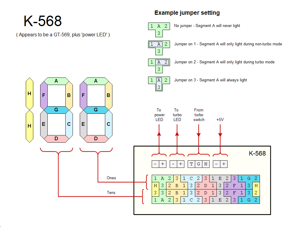
This has been on my to-do list for way too many years. I got the 568 as part of a lot the better part of 10 years ago. After that, I found a 230, then another. It took another little bit of time to cobble together a pair of working sampling plug-ins, and the special interconnect cable. Armed with all the pieces, I just couldn’t for the life of me to get the 230 spring to life. With 2 units of cards, the best combination I could get was some cursors moving on one channel, but nothing else.
Starting from the top, I checked the rails first. All was within tolerance. Next we start with the Buffer Card, where all the incoming signals from the scope land. In order for the 230 to start making measurements, it needs the horizontal sweep (the ‘low speed’ sweep), the sweep gate, and the clock pulses (one per sample). It also needs the mV & time settings on the vertical & horizontal plug-ins, and of course, the signal to be measured, but it doesn’t need those to spring into life.
All signals coming into and out of the Buffer Card were as expected. I started poking around at the Clock & Synchronizer Cards, because those generate a whole host of timing signals & gates that actually trigger the measurements. I honestly starting losing my place, because there are a lot of signals that need to be in the right state for the MEASURE signal to fire. I got tied up looking at the !END signal (! meaning compliment, shown with a line over the signal name in this documentation), which was needed to to start, and it started seeming like an infinite loop of sorts.
Oh, and a word on logic levels. This predates TTL logic, and uses active low logic, where a True state is represented by a low level between 0 – 2V, and a False state is represented by a high level between 6 – 12V. The convention in the manual is ‘High’ and ‘Low’, where High is False and Low is True. so for example the MEASURE signal goes Low for a measurement, and the !END signal goes High to indicate the end of a measurement cycle.
To make things even more confusing (and forgive me if I explain this incorrectly), negative logic changes the meaning of NAND and NOR gates, and they’re drawn differently in the schematics. See the NAND gate below. Electrically (shown in the second column), it behaves as a NOR gate, but in negative logic, it behaves as a NAND.
All this to say, there are a few things that make this a difficult machine to troubleshoot. So I cheated. I bought a 3rd, working unit. It arrived exceptionally well packed (so very grateful for that), with a nicely made interconnect cable (I already had a factory one), and it worked as advertised. Finally, I was able to see this beauty in action!
But I said I was going to fix a 230, so I set about starting to swap cards, this time, with a known good unit.
Swapping the Clock & Synchronizer Cards made no change. This supported my suspicion that perhaps they weren’t getting the right signal from the memory circuit. Swapped the memory, no change. The Start / Stop comparators send signals back to the clock, so I tried those next.
It’s always the last thing you try. With the B channel Memory & Zone Generator, I swapped the A Zone Generator with the known good card, and the unit spring to life. Through mechanisms I’m still trying to understand, if you have a bad Zone Generator Card installed with a good memory card, it can lock up the unit into the state I’d been seeing it in. And as luck would have it, I had three bad zone generator cards.
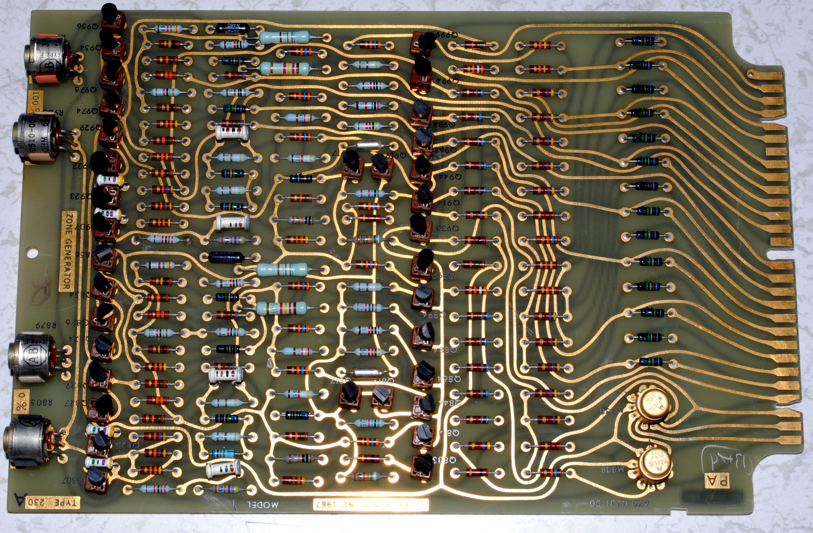
The Zone Generator Card has (2) logic ICs, and 36 transistors, a mix of NPN & PNP, all individually socketed.
The sockets are a blessing and a curse; It’s easy to swap transistors, but the sockets themselves also become a point of failure.
Sometimes, you want to sit down and dig into a schematic, come up with a hypothesis on why it’s not working, and start probing around to prove or disprove your theory. Other times you just want to brute force a problem, because it’s 11:00 PM, and manual labor is sometimes easier than critical thinking. So I set out to test every transistor in one of the bad cards to see if I could coax it back into the living.
I believe these to be unremarkable transistors, since the application is mostly simple low speed switching. In my model there was a mix of Tek model #s and manufacturer #s: NPN: 2N3904 / 151-0190 PNP: 2N3906 / 151-0188 I decided to test them on my 575 Curve Tracer at their operating voltage, fearing that perhaps the chinesium battery powered one might miss a fault, since these are operated across 50V rails. I found 2 culprits:
And with those replaced, the unit sprung to life!
So now we have 2 Zone Generator cards that at least let the unit run measurements, but both have problems. The Zone Generator card generates the areas on the displayed waveform where measurements are made, and show those at highlighted portions on the trace. A zone can be .5cm, 2cm, 4cm or 10cm long (or 12cm, but I’m not getting into that now). When the zone is .5cm, the average of that zone is returned; when it’s longer, the peak is returned.
The first card had an issue where the 0% zone would jump around, and not get to all the locations. We can see in the schematic, there’s a binary coded input coming from the zone position control. Because of the way it was jumping around, I suspected either the 2 or 4 bit, corresponding to Q864 or Q884. Q864 was bad, and replacing it gave me a fully functioning card.
The second card had an issue where the entirety of the 100% zone would be highlighted, so I could only see a movable cursor when only the 0% zone was selected.
This trace shows 2 good ZONE signals, and the incoming SWEEP GATE on the bottom, which I’m triggering from (thank god for 4 channel scopes). The negative pulses represent the position and width of the two zones.
The trace below shows a bad ZONE signal.
I’m seeing this signal coming from M938, but also going into it. Moving upstream, I check Q933. That’s OK. I pull and re-seat M938, and that seems to fix the issue. Now I have a cursor, but it has the same skip issue as the other card. The 100% zone transistors in question are Q964 & Q984. Both of these are good, but re-seating them fixes the issue. Like I said, those sockets are a blessing and a curse.
So now I have 2 more working Zone Generator cards, and a 2nd mostly functioning 230. It’s still wildly out of cal, and there are some quirks with the Nixie display, and cross channel time measurements, but I’ll get to those eventually.
This’ll be a quick one. The 111 is a pulse generator with ~ 500pS risetime. it has a pre-trigger output, which is adjustable from ~30nS to ~250nS. This makes it very easy to use an external trigger, and get the pulse centered on the screen.
Mine had 2 problems: 1) the pre-trigger delay wasn’t adjustable 2) the rate wasn’t adjustable, being fixed at ~200kHz or so.
Always check the rails first. The -15V line was down around -9V. I did a quick test of the Zener diode, which had to be done with a power supply, out of circuit.
The multivibrator portion of the circuit was adjusting, but the avalanche section that generates the sharp pulse* pre-trigger generator was oscillating in free-run, not taking it’s cue from that multivibrator.
Next I decided to check Q40, which turned out to be bad, showing up on my chinesium tester as 2 diodes.
I decided to just jam some basic bitch PNP transistor in there to see if it would work. To my surprise, it did!
* Edit: Q40 is not running in avalanche, that’s Q84. It would have been very lucky if some random transistor was capable of generating a sharp, predictable avalanche pulse.
Now I’ve got adjustable pre-triggering at 500pS, which has been useful for testing out some of my sampling plugins.
This is a continuation of an effort started a few years back. I had purchased one of these off eBay, but found that only every other bit would get stored. The troubleshooting steps in the manual indicated that this meant either a bad A3 buffer or A4 controller card. Although the schematics are included, there are no board-level troubleshooting instructions, or detailed theory of operation. Furthermore, HP says to not even return these boards for repair, simply discard them and they will send replacements. I because they’re made up of inexpensive 74LSxx series chips, even back in the late 70’s when the device was built, it would not be economically viable to have a technician spend their time diagnosing and repairing these boards. Yet that’s what I’m going to attempt.
When I first dug into this, I soldered dozens of little jumpers of magnet wire to various pins so I could probe the inner workings while the card was inserted. This got me nowhere, and so I shelved the project.
A year or two later, I saw another one come up on eBay, and one it for a surprisingly reasonable sum. It was listed “as-is, for parts”, but I figured I’d take the risk. Although in worse physical shape, this unit actually was fully functional. So now armed with a set of working cards, I was able to troubleshoot the bad unit.
Swapping cards, I was able to confirm that A3 was the problem. Fortunately, this card is accessible in place if you remove the HPIB (GPIB) card, which will not hinder operation. This finally let me probe the device in action.
The A3 board is essentially the edit buffer. Bits are read in, displayed on the front panel, edited, and then placed back into memory. The read & write is done serially, so there’s a shift register made up of 7474 flip-flops, and 7451 And & Nor gates that allow for the bits to be modified. The circuit is split up into even & odd sections, each with their own clock, serial in & out lines, and a few other control signals. (note the odd symbol for a NOR gate in the schematic below).
I first suspected the the flip-flops, so I unsoldered all of them, and installed sockets. I tested them in a little chinesium chip-tester, and one of them was bad, but the problem remained. I turned my attention to the and / nor gates, which unfortunately my little tester didn’t support. I wired up my 16500 Logic Analyzer to the output of each of those gates, and found that U32 was glitching. After replacing that I had what seemed like two working units.
Maybe this happened during repair, or maybe it was an issue that I didn’t catch at first, but now on the second unit (the one I thought was perfect), The 16th bit now mirrors the 2nd bit, on all words. This problem seems to follow card A4, which is not accessible when installed. It’s also a more complex circuit.
A4 card, partial schematic
I flipped the unit on it’s side, so I could start probing the edge connectors. On the analyzer, I’ll designate the last pin on the pod as PROBE, so I can move it around looking for interesting signals. When I find one, I’ll add a grabber to the next free line on the pod, and add it on the trace. I have it in continuous capture mode, to trigger on the clock signal (which only runs during a load or fetch). I turned my attention to J1-8 & J1-5, which are odd & even lines out to the RAM card. I expected them to look similar, but they don’t.
The odd line, which is working, seems to be in phase with it’s clock (this is showing no bits active), while the even one looks different.
I expected to see a similar pattern as the odd line on both lines of the good unit. I was wrong.
It looks totally different. Not shown here, but when there are bits selected on the bad unit, I’m seeing short glitch pulses on both the odd & even lines. Those are not evident on the working unit.
So without being able to dig deeper into the circuit while it’s working, I’m at a bit of a loss. For the time being, I’m going to be content with one working unit and one parts unit.
I decided the next step would be to build an extender card so I can freely probe both good & bad units while in operation. The edge connectors are 3.96mm pitch (?!), and I found 4 on eBay at a reasonable sum. They’re right angle connectors, but I’ll make ’em work. The bigger annoyance is there are jumper cables between cards along the top, so I both need to make an extender for those to connect to card A4, and I need to accommodate cables that need to pass across A4, without having to extend a bunch of other jumpers. I think I’ll design this card with a large enough hole in it. It’ll be mildly annoying, and I think a job left to Future Paul (screw that guy…).
2 years ago, I attempted to troubleshoot and repair an intensity modulation issue on my 564, but ended up giving up after a few unsuccessful attempts. I had replaced a few power supply caps, and all voltages & ripple were within spec. I thought maybe it could be an issue with the CRT? Last month, a spare CRT popped up 30 miles away for $40, so I grabbed it. I made the swap, and the issue remained.
I have since changed out the remainder of the electrolytic caps in all ‘low voltage’ supplies (all but the -12.2V – I don’t have a good way to mount new caps, and the ripple is really non-existent). I swapped the vertical and horizontal plugins, and never saw the issue, but I think this is a red herring, as when I put just the vertical plugin in the horizontal slot and feed it a 60Hz ramp, I do see the issue. I did this 2 years ago, and confirmed it today. The other thing I did to eliminate my suspicion of the horizontal plugin was to pull the transistor that drives the intensifying signal, Q294. When I pulled it, the issue diminished a little bit, but was still present.
Other things that didn’t work:
Disconnecting the intensifying pulse input – had to leave R838 & R839 connected, otherwise the beam intensity was unstable.
Maybe there was some heater to cathode leakage in the HV regulator tube? I swapped it out with a 12AU7 (similar pin out, close enough performance), the same issue occurred.
The ripple of on the primary of the HV transformer seems negligible, and in line with what I’d expect on a simple unregulated supply. Allowable ripple isn’t listed on the manual like it is for the other rails.
May be on to something: I’m seeing at least 5V of ripple on the grid of V800.
I thought the ripple on the 300V supply was in spec, but I just noticed a filter cap I missed on the other side of the regulator, that’s tucked away in the back of the scope. No change after swapping out that cap, but I think we’re getting closer. When I see problem, I’m also seeing ripple measurements jumping around. When the trace is solid, the ripple is rock steady at less than 5mV.
Things to suspect next:
V674, the 6AU6 error amplifier Nope.
V677, the 6AS7 series pass tube Damn, this was looking like the culprit at first, but the issue returned not after not too long. Swapped the old tube back in and issue eventually returned.
C670 blocking cap – worth a try? Nope.
Worth noting that we can still see the ripple on the 300V rail even if we pull the plug-in.
Turning our attention back to the HV section, looking at the input of the HV regulator error amp, before R816. It’s bang-on at -106V. The problem has been intermittent, and hasn’t happened for a few minutes since I gave that area of the HV supply a blast with cold air (compressed air upside down). Yep, OK, it’s back and the ripple is evident here as well – still not clear if we’re getting closer to the cause, or are just seeing the effect on the +300V rail. OK, this kind of sucks, but I’m getting to the point in the program where we just start swapping out caps. Also waiting on a 6CZ5 to swap out V800
C841 – .047u – no change
C849 – .001u – no change
C801 – 0.2u ? just a disc cap
C807 – .001u – says it needs to be 600V, but there’s only ~500V across it. Gonna risk a 600V for now.
SOLVED. It was V634. The 6DJ8 in the -150V supply. The supply that has NOTHING TO DO with any of the HV Circuits, and which exhibited NO RIPPLE. F*&k, this was a hard-earned win.
Side note – I nuked Q294 while I was troubleshooting – it runs the intensifying pulse, and I was yanking it and stuffing it back in live. I put in some basic bitch NPN transistor and it works fine.