The idea of designing a programmable, high voltage power supply came to me after hobbling together all of the gak that I needed for reforming old electrolytic capacitors. There are a few good examples circuits out there for home-built reformers, but none of them were exactly what I was looking for. I’m into sure how digital or programmable I want this to be, but my thought was that if there was at least some logging capabilities, I could easily plot curves of the process and maybe tease out some interesting trends.
Without thinking too much, I’m going to spitball a list of possible features:
0 – 600v DC
10-20mA max, with current limiting. 20mA is probably a lot for reforming, but maybe this would also see use as a general lab supply
Current & voltage meters
Logging current, voltage setting, and voltage across terminals, with timestamps (rtc needed?)
Discharge resistor (variable ?)
Ability to set a maximum voltage setting, and automatic incrementing of voltage when current drops below a threshold
Voltage regulation? This probably won’t have the effect I’ll usually want when reforming (i.e. I wouldn’t want the supply chase to match a target level), so perhaps it wants to be disable-able, if that’s even possible.
Some questions:
Form factor – rack mount gear is cool, but often impractical
UI – keypad entry? Menus?
Meters? Ideally analog, if possible, with switchable ranges.
Tube or solid state?
Research:
Heathkit PS-3 Power supply schematic – I feel like there may actually be one of these up at the “upstate home for wayward oscilloscopes” (aka, Mom’s basement) as a side note, I also have an unbuilt Heathkit PS-4 waiting for a nice rainy day (or my retirement) </brag>
Side note – I’m trying to sort out the difference between blog posts, pages(or posts) about actual projects, and pages(or posts) about specific pieces of equipment, so there will likely be some organizational turmoil over the coming months.
Posted on by wpadmin -- Last edited on June 9, 2015
Taking a break from scopes for a change, I decided to examine a piece I picked up a while back. Behold the Model 1519 Pulse Counter, by Transistor Specialties.
I really can’t find much of anything useful about this product or company, though it looks like they produced a handful of counters during their seemingly brief life.
A side note: A quick search yielded this gem of a site – americanradiohistory.com which has scans of a number of old electronics magazines. A trove of geeky goodness, I’ve just downloaded a heap of old ‘Electronics World’ issues from the 60’s for my upcoming 9 hour flight.
Underneath the hood reveals what you’d expect from an counting instrument of this era.
Two beautiful hand-wired looms connect the tube sockets to to the cards, one for each channel.
On the rear are some connections to allow each channel to be started, stopped, or reset remotely, as well as two honking 40 pin Cannon connectors I’ve never seen before. I’m assuming they convey the current count somehow. Maybe BCD?
There are 16 identically sized cards. the first two are identical, the third one is unique, and the remaining 14 are identical pairs – I’m guessing a dual counter & dual driver for each of the 7 digits. Here’s one of the counter(?) cards removed. This thing is 100% discrete logic; nothing but resistors, caps, diodes & transistors to be found in here.
Note the card connectors, they meet with identical conductors on the ‘backplane’ connectors, which are rotated 90°. They are similar in appearance, size & operation as the center contact on 125Ω GR-874 connectors.
Update 6/9: Kurt pointed out that these are the same connectors found on the cards of the 6R1, the digital readout plug-in for the Tektronix 567. Do check out that 6R1 page, it’s exquisitely documented.
This is a closeup of one of the two input cards, notice the thermally bonded transistors.
These are all single-sided boards, with hand drawn layouts, and somewhat ham-fisted soldering.
This line filter appears to have been added much later. Because the line cord had been cut, I tacked on an edison tail I had lying around.
Needless Disclaimer: this is temporary wiring for testing purposes. Do not lick.
Lets fire ‘er up on a variac. Around 60v, it starts to come to life.
At full line voltage, it’s stable.
Hitting the reset button zeros out the displays.
I couldn’t get this to trigger on any signal, sine or pulse, from the dozens of hertz to hundreds of kilohertz. I started metering around on the input board, and there was gobs of 60 cycle that the incoming signal was getting lost in, so I started checking the caps with my trusty Heath IT-28 (which is really deserved of it’s own post).
The big-ass 10,000 uf cap on the low voltage supply proved to be faulty. Though it passed a leakage test, it exhibited a very low power factor (which equates to a high equivalent series resistance).
A smaller replacement was en route when I just so happed to spy a beautiful 15,000 uf cap of the same form factor at the HOSARC ham fest. $8? sure.
I’m still getting some 60 cycle when I poke around, but it’s now where near as bad as it was. Still no worky, the signal seems to die somewhere in the input card. I haven’t decided how much I care about getting that part of it working; I’m more interested in figuring out how to get it to display a number, and if there was a way I could do that without having to send the requisite number of pulses, that’d be swell.
installing and removing the input cards while running causes the numbers to increase, so presumably something is counting. I still haven’t figured out what that shorter card in the middle does, but removing an inserting that has similar effects.
I’m assuming that each card pair is a decade counter and display driver respectively. I might suck it up and try to draw out a pair. I have some readings from the backplane, but I think I’ll pick up with that on the next post.
One more thing: as I was reading Kurt’s post on the 6R1, I realized that the circuit is probably very similar to the counter cads in the 6R1.
Here it is in a rather compromising position, getting its caps checked.
“Turn your head and cough”
What’s a Tektronix 519? Arguably the biggest, baddest, ballsiest oscilloscope ever fucking made. Designed over 50 years ago, and built in extremely limited numbers through the 60s and early 70s, it was unsurpassed in its ability to capture extremely fast, transient or one-shot events, as well as repetitive signals of up to 1GHz, in real time.
It is a machine unlike anything Tektronix had ever made, and due to the fact that it was the pet project of a senior engineer working free from the boundaries of the institution’s design team, it bared a only casual resemblance to the rest of their line-up.
Because the variac I have easy access to is only good for 5 amps or so (and gets a bit toasty at that), I decided to just go for it, and hit it with full mains voltage. Side note: I really need to get that 20A variac out of storage and wired up. Nothing.
Checked the fuse, and there was a blown 4 amp slo-blow. Based on the markings, a 4 amp fuse suggests that the unit was being used at 240v, otherwise it would have had a 7 amp fuse for 120v operation. I carefully rolled the unit over to remove the bottom panel and expose the transformer wiring. To my surprise, the transformer was wired for 120v operation. I’m just preying no one tried to power this thing up on 240v, but I suspect not. With the exception of a fine layer of dust, the interior is immaculate, and shows no signs of distressed components. I’m also pretty sure I heard a brief ‘chunk’ of the blower try to start over the heavy click of the switch, so it is possible that it was I who blew the incorrectly installed fuse.
I’m taking this as a sign that I should do a more thorough inspection before firing this thing up for the first time in god only knows how many years. With the chassis still rolled over (I would like to move this heavy, fragile, priceless relic as little as possible!), I went to work testing the supply caps who’s terminals are accessed on the underside of the chassis. These are the ‘low voltage’ supplies, covering about 10 different ranges between -250v through +650v. The high voltage supplies are -4,100v and +20,000v (!!).
Here’s my updated test & reforming rig. My heathkit IT-28 capacitor checker, my trusty old Fluke 83 for measuring voltage across the cap, and a Bell & Howell multimeter for measuring current. This is a kludge to say the least, but it’s what I had on hand. A programmable, high voltage power supply tailored for cap reforming sounds like an interesting next project. In the mean time, this will have to do.
Here’s a closeup showing the charge line from the calibration step generator. It’s in the way and making it difficult to disconnect the caps, lets see if we can remove it.
Removing the screws in the GR-874 connector…
And loosening the clamps on the charge line…
…let me carefully pull the charge line out through the front panel.
Here it is on my bench with its outer sleeve removed.
Here’s the coil that wraps around the charge line and triggers the reed relay within it. It’s also worth noting that the bit of corrosion seen in the photo below represents the only bit of it I’ve found anywhere in here so far.
I started with C613, then moved on to C661,2,3, which is three 125uf caps in parallel. I left the cap fully in-circuit for some of my early tests.
Once I disconnect the + side of the cap, I connect the reforming circuit and start out at 50v and slowly work up to the rated voltage of the cap. As the voltage increases, it takes longer for the current to drop to an acceptable level. As far as what is considered acceptable leakage current, I’ve read a variety of opinions. This site has a handy chart, which suggests that anything under a few mA is acceptable for these beastly 125uf, 450v caps. I’ll move on to the next higher voltage when the leakage current drops below a mA, then hold at the rated voltage until the current levels off. So far, that’s been on the order of a few hundred uA, which is great for 45+ year old caps.
Ready for smoke test
so is Fire Chicken
YEAHHHH!
I was dorky enough to record a video. Here it is in all of it’s dark, shaky, glory. Pardon the occasional explicative, I was very excited.
I was able to get a free running trace, at all but one sweep speed. The trace was crisp, and I was able to move it as expected via the positioning controls. It is a shade of blue that I have never seen on a scope CRT before (P11 phosphor). The 24kV accelerating potential made for a staticy, zappy sound when the relay kicked in to power the ‘low’ and high voltage supplies.
I hooked up the rate generator to the input. While increasing the multiplier control, I heard a snap, and saw a white glow in V717, a 77http://paulcarbone.com/blog/wp-admin/post.php?post=409&action=edit34/6GE8 which is part of the +450V supply. This I believe is completely unrelated, but obviously worth investigating.
Next Steps:
Check V717 in my tube tester
Check the output of the Rate Generator & Step generator with either my 7834, or my 661 (heheheee).
See if I can get it to trigger on anything.
V717 is a 7734/6GE8, a combo triode + pentode. What claims to be the latest settings sheet for my Heathkit TT-1 tube tester does not have this tube. This is the second time that’s happened this month, and it’s starting to chap my ass. I have a few other testers that are in need of resurrection, but I thought that the TT-1 was the most comprehensive. I’ll have to double check next time I’m back up at ‘The House for Wayward Oscilloscopes’. grrr…. Lets just put it back in and check the 450v line. Perhaps this transient event I witnessed was not actually damaging to the tube.
Here’s the output of the Rate Generator on my 7603
With Function set to ‘Sync’, I was able to get this trace at 50nS / cm. Very sporadic and required constant fiddling with the sync & vernier controls.
After some more fiddling, I was able to get this trace at 10nS. 20nS is the one that doesn’t work.
That’s insane. I’ve never seen a trace that sharp before. This thing is a monster.
As I’ve previously mentioned, I’m in possession of no less then three, complete, working 7D01+ Display Formatter pairs (2 DF01s & 1DF02). I got my original one working, keeping one as a maintenance spare / parts unit, and tearing down & stripping the final one.
It did take a moment of inward reflection before I decided to sacrifice a Tektronix product, but I decided:
It’s not particularly rare; You’ll always see one or two on eBay. Though they’re asking price is usually upwards of $200 (or sometimes more, which is just silly), they really only sell for about $50 – $100. They were made from 1977 to 1985, though I don’t know how many were actually made.
It’s been an interesting circuit to get to know, and further poking will be educational.
It’s a trove of useful parts, including a beautiful ceramic & gold MC6800 CPU in the DF01, 20+ really nice toggle switches, tons of discrete logic, a dual concentric encoder, and some dual concentric pots. I’ve already made a rudimentary 1Mhz clock circuit using some of it’s parts.
It’ll be fun, and I’ll take some pictures for here and the wiki.
Did I mention I have three of them?
The front panel circuit board is called out as the recognizer & trigger selector. It also has the differential line receivers (Motorola MC10216) which are the input buffers for the P6451 probes. The probes connect via 2 25-pin micro sub-D connectors.
After my previous antics with the 7834 readout system, the outcome was:
U3401 Zeros logic & memory – tek part 155-0018 – the original culprit. Replaced with one from ebay.
U3418 Column decoder – tek part 155-0014, which I think I killed during repairs. Replaced with one from ebay.
U3477 7402 quad 2 input NOR gate – smoked during repairs. Replaced with a 74ALS02 from stock.
It turned out U3232, the row data switch that cycles through the 8 plugin display channels was bad as well, botching the readout in horizontal A bottom, and horizontal B top & bottom. Replacement sourced from ebay.
So far, I’ve spent $50 on the scope, and another $50 or so on replacement chips. Still not bad at all.
Here’s a few shots using the 7B85’s delta time feature, which lets you do fun things like measure frequency, rise-time, and pulse-width directly using the on-screen delay time read-out. Thanks to Peter on the TekWiki who’s entry on the 7B85 pointed out these features.
These photos are of a rudimentary clock circuit I made using parts from the DF01
OK, so sometimes I search craigslist for:
Oscilloscope
Tektronix
Heathkit
Well this weekend I got lucky, and found someone selling some unbuilt heathkits for a great price. He also had a few Archer 5V power supply kits for sale, which I’d never seen before, appeared complete, and were reasonably priced. I bought two, here’s the one that I’m going to build.
In it’s original box:
Unboxing:
Well, it’s clear how the manual was folded in the box.
The enclosure and (stick-on) front panel was in flawless shape.
The circuit board showed some signs of age. One or two pads lifted a little while soldering, but nothing tragic.
Components neatly packed within the chassis
Box-O-Parts
The Build
The screw heads were proud of the surface, which would have compromised the front panel application.
And then I remembered I had a drill press and a countersink bit.
The manual suggests soldering the transformer and rectifier together on the bench based on a rough drawing, but given the rigidity of the wire and the tight dimensions, it seemed a better plan was to at least tack-solder the two together while temporarily in situ.
Transformer & rectifier permanently mounted.
All other elements mounted.
Testing
Brought it up on the variac with no troubles. I was able to trim the voltage to 5.46V, and it held across a wide range of line voltages, without a load.
I was unable to calibrate the unit to 5.0V with the stock parts, so first I re-installed the circuit board with the bottom screws in the top holes, so it was easier to access.
Then I soldered in some jumpers in place of R2 and hooked up a decade box.
Then I soldered in some jumpers in place of R2 and hooked up a decade box. 1.8k would have put 5.0v directly in the middle of the trimpot range, but I didn’t have any so I got away with 2k. I was able calibrate it to 5.0v, and so far it’s been performing without trouble.
You’ll notice that there are actually 4 terminals on this supply. That’s because this is a ‘sensing power supply’, which allows it to compensate for losses in the wires from the power supply to the load. The two sense lines can be of a much lower gauge then the supply wires, since they’re not passing any appreciable current. They sense the voltage at the load, and are part of the regulation feedback circuit. The regulator’s target is 5v at the load so if it’s gotta output 6.3v to overcome 1.3v of drop, then it happily obliges.
In addition to being fused both at the line side and low voltage side, it also has short circuit protection.
Oh, and here’s the schematic.
I think this is going to be a nice supply for LED tape experimentation.
This was actually the first scope I got as “an Adult”. I think I paid about $100 for it about 6 years ago. Since then, it’s been my daily use scope, since it fits atop a rolling art-cart under my bench.
Everything works great, except the B sweep only triggers on ‘starts after delay’, not ‘triggerable after delay’, which means there’s something fishy towards the front end of the B trigger circuit.
Great write-up of 454 triggering diagnosis here. Punch-line: it was the tunnel-diode.
replacement for 4.7ma tunnel diodes available on eBay, type GI304A, 10 pack en route.
Also suspected Nuvistor v633, type 8393. Substitution with a claimed-good tube didn’t change the issue, so I’m suspecting it less, but unfortunately I can’t locate the test parameters for the the 8393.
Found it for the 6cw4 (same pin-out?) Tube Plate Bias Fil. Meter Sig. Selectors R.P. Remarks
6CW4 C 7L 6.3 32 4 03050-0010-706 1430 Tr;X4.
Boom – An 8393 is a 7586 w/ a 13.5v filament. So, for the TT-1: Tube Plate Bias Fil. Meter Sig. Selectors R.P. Remarks
8393 O 7L 12 36 4 03050-0010-706 1140 Tr;X4.
UPDATE 5/3: Everything around that Nuvistor seems OK, but nothing is coming out of it, with either the original or replacement. They both test dead. So either:
1) I’m testing them wrong, and it’s something else in the circuit, or
2) I have two bad 8393s.
replacements en route, 3 for $45. Damn these things are getting expensive.
I also realized that this Nuvistor is a part of the signal chain when in XY mode, which I could never get working.
UPDATE 5/8: Replacing v633 Nuvistor fixed the X/Y mode, but ‘B’ is still not triggering on it’s own, so there’s still some drama in the triggering circuit.
I figured it was time to break this off into it’s own post. After some initial troubleshooting, I’d determined that the CRT was the source of the intensity and focus flickering I was experiencing.
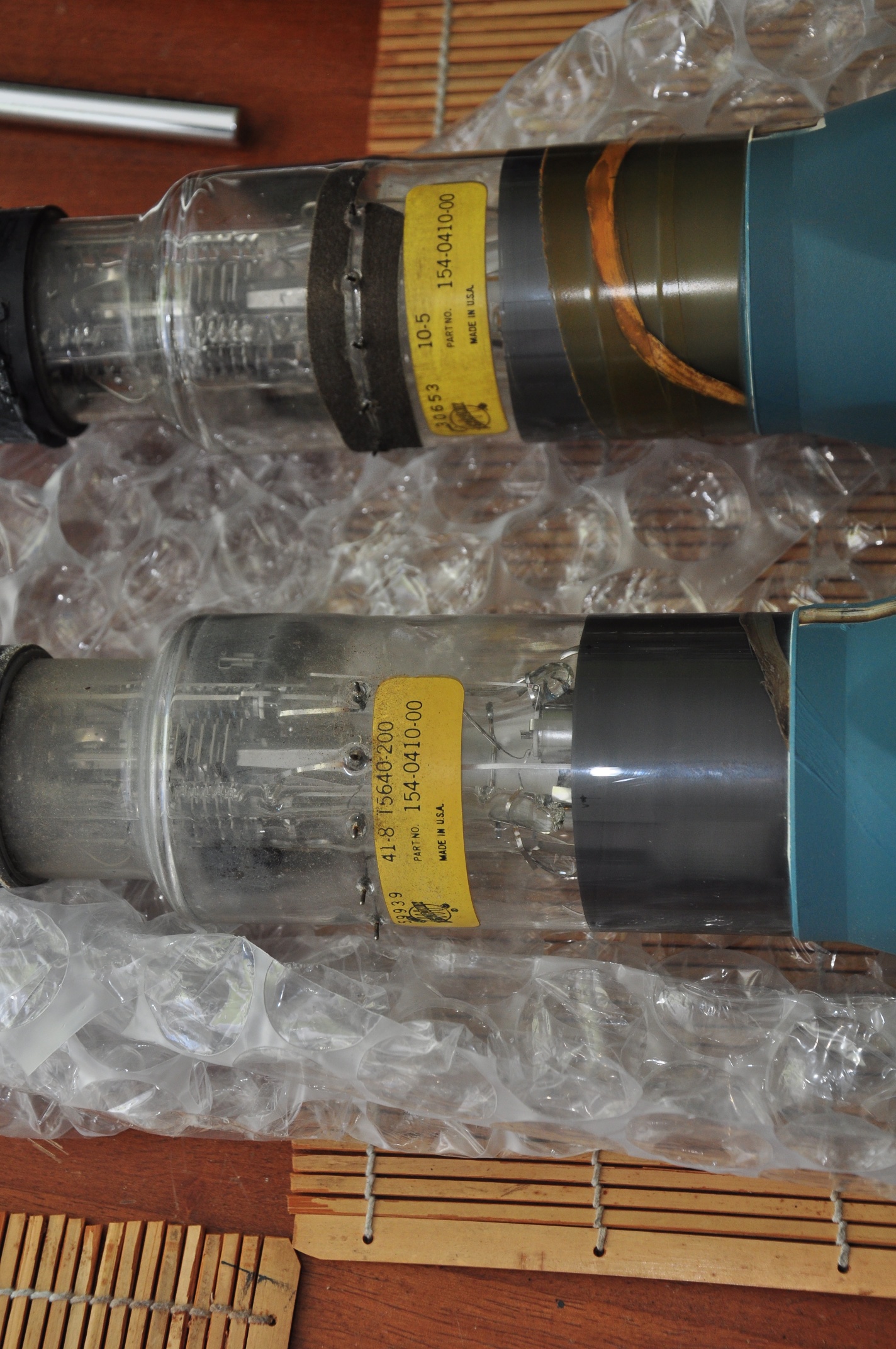
I ordered a replacement I found on eBay, and it arrived yesterday, safely and extremely well packed: Here it is after unbubblewrapping:
I proceeded to carefully disconnect and remove the old CRT, leaving a gaping hole in the business end of the scope:
Note the electrode connectors that press against pads on the neck of the CRT. in front of that is the trace rotation coil, wrapped around a black plastic bobbin.
I compared the two to make sure they were in fact identical. Spoiler alert: They’re not. The part# is the same, but there are other markings that differ.
OK though, same part number, we should be good, right? Hmm.. one of these things is not like the other:
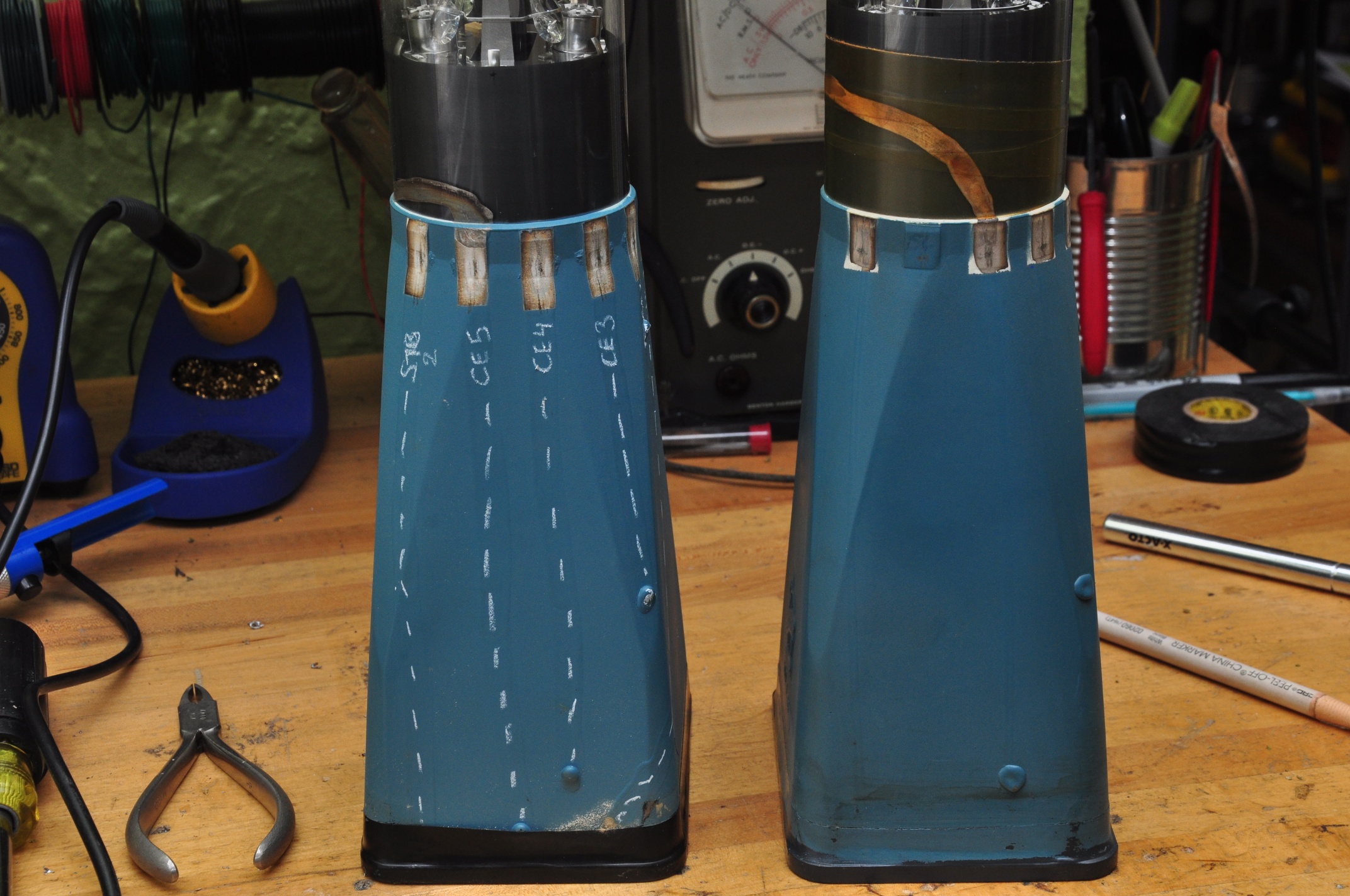
There are 6 pads around the old CRT, and 6 corresponding contacts on the scope. The new screen is missing the 2nd (or 5th?) pad. Additionally, it looks like there’s a conductive trace coming out of the left of the 2nd pad on the old CRT that’s attached to the 3rd trace on the new one. I needed to do a little more investigation before I was comfortable just shoving in the new screen and hoping for the best.
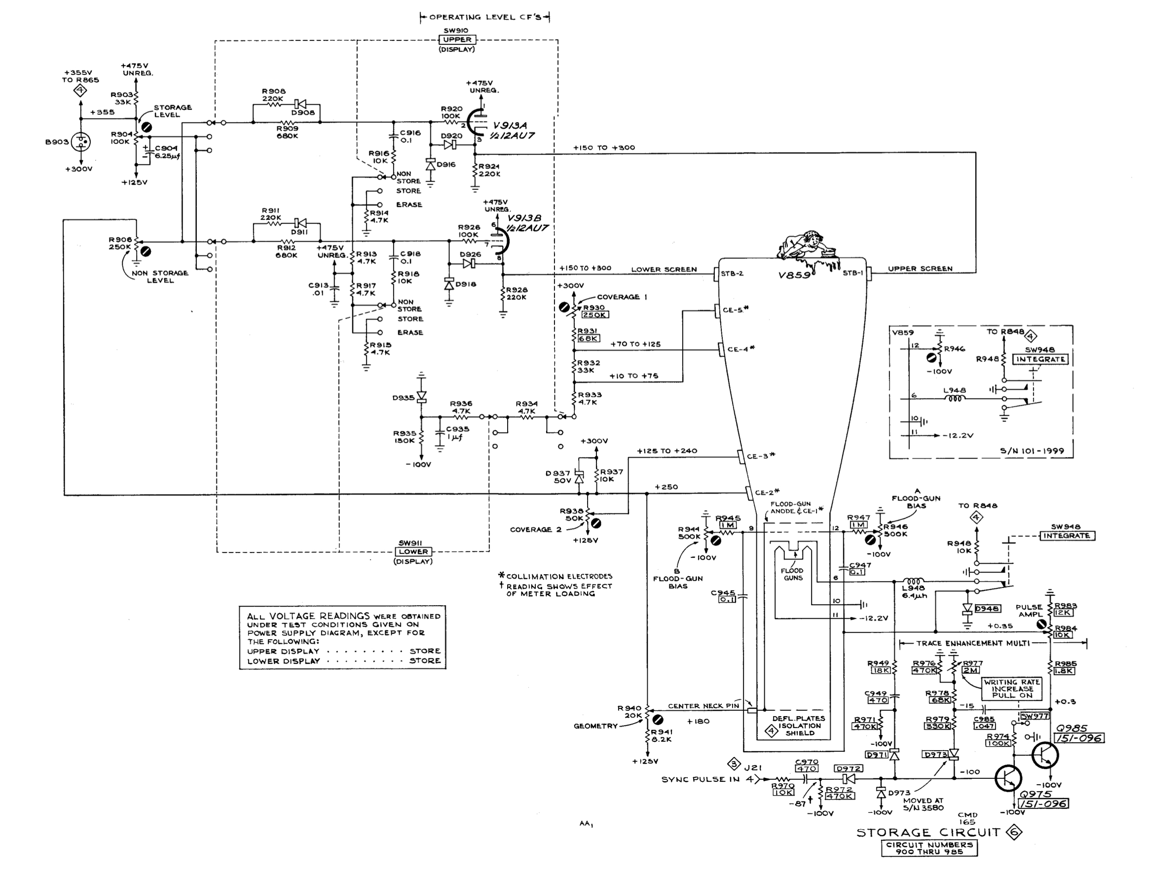
These connections are all a part of the storage circuitry, as seen in the schematic below.
After a bit of cold metering in the scope, I was able to determine which connections were which on the CRT, and I marked them with a grease pencil:
So pins 1 & 6 (counting counterclockwise from the bottom in the scope) are STR1 & STR2, the upper and lower storage targets, while 2 – 5 are CE1 – CE5, the collimation electrodes. I’ve marked the path of the conductive traces so they’re more visible, you can see that they each terminate at the connection to their respective grids.
Feeling confident enough, I carefully installed the new CRT and brought it up slowly on the variac. I got a beautifully sharp trace that didn’t flinch, even with gentle taps on the tube:
As you can see, intensified mode works great.
One of my other recent purchases was a Heathkit TT-1 Tube tester. I started out the previous version diagnosing a smoking resistor in the storage section power supply. Now I had a way to check the tube. Both sides of the 12AT7 checked out OK on mutual conductance and shorts, but one side failed the grid current test (exhibiting lots of it). AH HA!!
I suspect the grid current was causing excessive draw on the 475v supply, which is why the resistor was overheating. I replaced the tube and slowly brought it up on the variac – low and behold the resistor remained cool.
Wait a minute, a 12AT7? The schematic (and nicely silkscreened chassis) calls for a 12AU7. Huh, I didn’t realize that upon first inspection. The 12AT7 has a much higher gain then the 12AU7, and I wonder if that led to the premature failure of the tube. It now has the correct tube.
Next on the hitlist:
Documenting the storage functionality. It sort of works, but needs some attention
Understanding the grid current test on the TT-1
Sourcing a replacement handle. I actually don’t mind going off-brand here, and would dig a custom replacement as long as it made use of the original mounting hardware.
Picked this up as a part of a larger lot, and was the first I attempted to power up. I did so stupidly, without a Variac. Quickly shut down after smelling smoke from R646, a 100Ω 1W resistor that’s a part of the unregulated 475v line. Metered it after the incident, and it appears to be OK.
Yanked the plugins and grabbed my newly re-wired Variac. as I rounded 50v, things started to spring to life – around 80v I got a spot on the CRT, and R646 was HOT. Shut ‘er down.
I think I’m going to yank all the tubes & transistors in the power supply, and check each supply one at a time, starting with the -100v supply. We start with the -100v because as with most Tek scopes of the era, the -100v (or -150v) supply was the one that all other supplies were referenced from. We’ll start with -100v, then +125v, then +300v. While the 475v supply is unregulated, it comes into close contact with some of the other supplies around the storage circuitry, which is also on the list of suspects. Just for a chuckle, remember all of these are considered ‘low voltage’ supplies 😉
With only the tubes in the -100v supply installed, I get -150v on the rail when line voltage is brought up to 115v. There’s about 90v across the gas regular tube instead of 80v. I’m not sure if this is because the 125v supply isn’t up? Furthermore, what’s with the pin 6 connection on the regulator tube?
With V667, V674 & V654 reinstalled, I can get the -100v power supply dialed into -100.0v.
Attempted to dial in the +125v supply but it jumps between 123.7v & 126v as I adjust the pot. 125.9v was as close as I could get it. Getting the +300v rail dialed in was no problem, same with the -12.2v supply.
420v unregulated reads 427v, 475v unregulated reads 485v with 115v line voltage.
Now I’m suspecting the problem is in the storage circuitry, since that appears to be the only thing powered from the 475v supply. As a side note, are these tin whiskers?
OK, with V800 & V814 installed, I get a spot on the CRT! Focus & astig controls change the spot shape, and location on the screen. When I get it as sharp as I can, the intensity control also makes the beam move around. Lets try a horizontal plugin.
SUCCESS! Lets try the vertical plug-in.
It needs a cal and cleaning, but all 4 traces seem to work somewhat. Even the delayed sweep seems to work:
So the trouble is in the storage circuitry.
After running for a while, the intensity started to jump around, became very bright, and the intensity control no longer functioned. Stay tuned for more…
10/12 UPDATE
it’s general intermittent intensity issues, stemming somewhere from the HV supply.
C830 & C832 measured around .0026u which correlates to the parts list, but not the schematic, which calls them out at .0068u
R842 ((2)2.7M+(2)3.3=12M) Measured 13M cold, measured open after about 15min operation, then slowly dropped the meter picked it up around 50M, and it’s almost all the way back down. Some metering in the early minutes after shutdown leads me to suspect one of the 3.3M resistors.
there’s a strong mechanical component to the problem; lightly pressing on the HV portion of the central chassis would drastically affect the intensity of the trace.
metering across the two neon bulbs I’d see anywhere between 50v & 120v that’s directly affected by the intensity control. In one flicker scenario, the intensity wavers but this voltage remains consistent. After being warmed up for about 20 min, the flickering would affect this voltage, causing the neon lights to fire
11/1 UPDATE:
I was wrong about the resistors, they read OK when immediately lifted from the circuit after power-down.
I’ve measured the HV supplies, and they seem consistent during the focus & intensity flickering, though measuring them does affect the trace (which I was surprised would happen with a 75MΩ probe impedance).
Screen voltage of V800 is around 65v for a normal trace at .2ms and can jump as high as 90v during a full bloom event.
As per the recommendation of Albert on the forum, I checked the V800 screen w/o the CRT connected, and it was around 65v.
Gently tapping on the chassis above the HV terminal strip does accentuate the issue, but I can’t find a component (either tube or passive) that responds specifically to some more directed tapping. I’ve re-seated the CRT socket, but it seems those wires are particularly sensitive to giggling. I opened up the the socket, and the pins look good.
It turns out tapping directly on the CRT shield or neck causes the biggest change in intensity, so now I’m fearing it’s a mechanical problem with the CRT. I can wiggle the CRT or leads to get a good trace, but it quickly goes back to incessant flickering. This is getting really frusturating. I think the only fix might be:
1) Sourcing a new CRT
2) Hitting it with a brick until I feel better
UPDATE: There’s a replacement CRT en route, part # 154-0410-00 (P31 phosphor, same as mine). CRT replacement chronicled here
Picked this up about a year ago, and used it solely with my then slightly misbehaving 7D01, in combination with the DF01 Display Formatter. Because the DF01 was gen’ing all the characters, I never noticed that the readout feature was misbehaving until I went to use a pair of conventional plugins.
There’s a few things wrong with this:
1) The characters are incorrect
2) The top and bottom of the vertical plugin readout are supposed to be for channels 1 and 2 respectively, but they both seem to respond to channel 1 only.
Regarding the incorrect characters, it appears that from this table, the characters are shifted one to the left of what they should be. ‘0S’ should read ‘1V’, and ‘4m’ should read ‘5u’ Columns and rows are selected by way of a current loop between the plug-in and mainframe, using .1ma steps between 0 & .9ma.
Oh, hello:
“Score!” I thought, but sadly turning it does nothing. Also, my columns are the issue, not the rows. UPDATE – Column Match doesn’t do anything either.
So I started poking around with my 7D20 and found something strange coming out of the U3433, the custom timer chip:
Note the often overlooked screen annotation feature on the earlier 7k scopes 😉
So there should be a negative going pulse on pin 16 that corresponds to the waveform on pin 10. Also note that negative portion of the waveform on page 10 are shorter where the pin 10 pulse is missing. I went ahead and ordered a replacement U3433, we’ll see if that does anything. In the mean time, I’m off to the tek message board…
09/16 UPDATE:
Heard back form a gentleman on the forum:
1) What I’m seeing on the output of U3433 is not uncommon and due to display skip (which is described in the manual, I just have to wrap my head around it)
2) He recommended swapping U3429 row decoder & U3418 column decoder – did that, no change.
3) He recommended swapping U3232 row data switch and U3263 column data switch. oh fuck, those are BURIED. Standby for some fun.
9/16 UPDATE:
The power supply slides right out, making U3232 & U3263 accessible. Well played Tektronix. Swapping them made no change.
Here’s the bottom of the scope – note the plastic rails on the bottom of the PS on the left. One of those was loose and keeping the PS from sliding out. Had to pop the bottom cover off to free it.
resocketing a few of the transistors fixed the missing readouts on the left horizontal bay, and the upper/lower duplication I was seeing. Now every bay has it’s readout, it’s just wrong.
9/17 UPDATE:
what’s supposed to be +4.4v on pin 9 into column decoder U3418 is only +3.84v
what’s supposed to be +14.5v on pin 10 is 14.8v
9/19 UPDATE:
Well, this has suddenly turned into a larger problem. Yesterday I’d gotten some of the characters to change by paralleling in a decade substitution box. Today I tried again but paralleled the wrong resistor (R3418), and I as was trying to pull the lead (live – dumb) I shorted something, heard a snap from the power supply, and the display went crazy, then dark. I shut it down, and when I started it back up, U3447 started to release it’s magic smoke.
I can only suspect that one of the legs of the power supply has gone awry, but the power supply wont fire up when not under load. I’m at a complete loss as to what to do next…
OK – moving on from despair…
With the readout board fully disconnected, the scope powers up and behaves normally (sans readout). IMPORTANT NOTE: When disconnecting the mini coax connectors, note that some of them have shield potentials of 15v, so take care to make sure they don’t touch the chassis.
9/20 UPDATE:
It was U3401 – zeros logic & memory.
I decided to swap out one chip at a time from the 7834 to the known good 7603, in order to asses the damage. When I got to U3401, the same problem showed up on the 7603. Total facepalm for not doing that earlier. All other chips were OK, with the exception of U3418, the column decoder. So now I’m down:
U3418 Column decoder – tek part 155-0014
U3401 Zeros logic & memory – tek part 155-0018
U3477 7402 quad 2 input NOR gate – I only have an 74ALS02, not sure if that’ll cut it.
Replacements for U3418 & U3401 en route
9/20 UPDATE:
74ALS02 is fine for U3477, tried it in the 7603 (thanks David)
In retrospect, I should have suspected U3401 given that ‘>’ worked but ‘IDENTIFY’ didn’t, since it’s U3401 that signals the column & row data switches to run through the sequence of characters to spell ‘IDENTIFY’.
9/25 UPDATE:
After an in situ check of components around the affected areas, I pulled U3418 & U3401 from the 7603 and installed them in the 7834, held my breath, and power’d it up. All good. The soon-to-arrive replacements will make the 7603 whole again, though for now it doesn’t really matter, since it’s really only host to my 7D20 & 7D01.