TU-75B Wattmeter repair

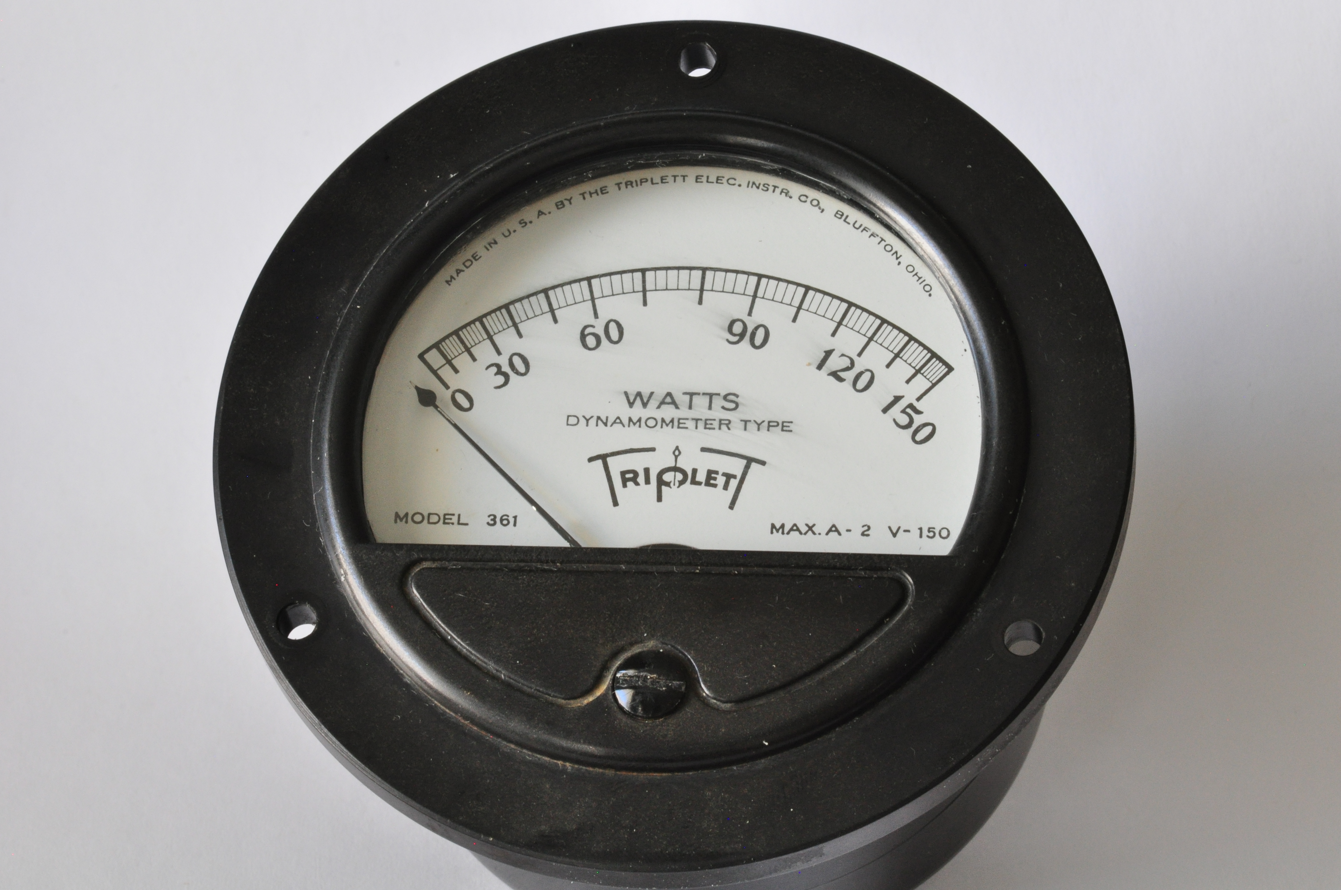
As mentioned in my earlier post, the glass face had broken loose in the wattmeter on my TU-75B Variac.  I managed to re-attach the glass, learn a bit about this particular meter movement, and take a few nice shots while I had the unit apart.

First order of business was to clean out the gasketing material that originally held the glass in place.  It was black and brittle and not too terrible to scrape out of the inside of the meter body.  <sidenote> I do need to get a better understanding of what these original materials are – a table of common materials and finishes of the era, along with how to clean them and affix them would be a great resource to develop </sidenote>

IMG_4695.JPG

With the inside cleaned, the glass seated flush against the back of the opening.  I scratched up the inside wall a bit with the exacto knife, but it’s not visible when the meter is assembled.

IMG_4698.JPG

I picked up some Permatex 81730 glass sealant, which was recommended in this post about re-seating vacuum tube bases.  This video about re-seating CRT socket bases was where I first heard about it while researching how to reconnect the base on my OS-8/CU scope.  I figured I’d use it for this application as well, since it’s a similar plastic to glass connection (albeit without the heat of a CRT).  It was a little difficult to work with for this particular application; I wish it was a little more viscous and a little less sticky.  I also have some Permatex 80008 Form-a-Gasket sealant, which perhaps I’ll try next time.  The other gauge I have to re-face is going to be done with acrylic, so that that may be a different type of adhesive.  I was very conservative in applying the permatex, since it was easy to spread to visible parts of the glass and difficult to clean up while it was setting.

IMG_4704.JPG


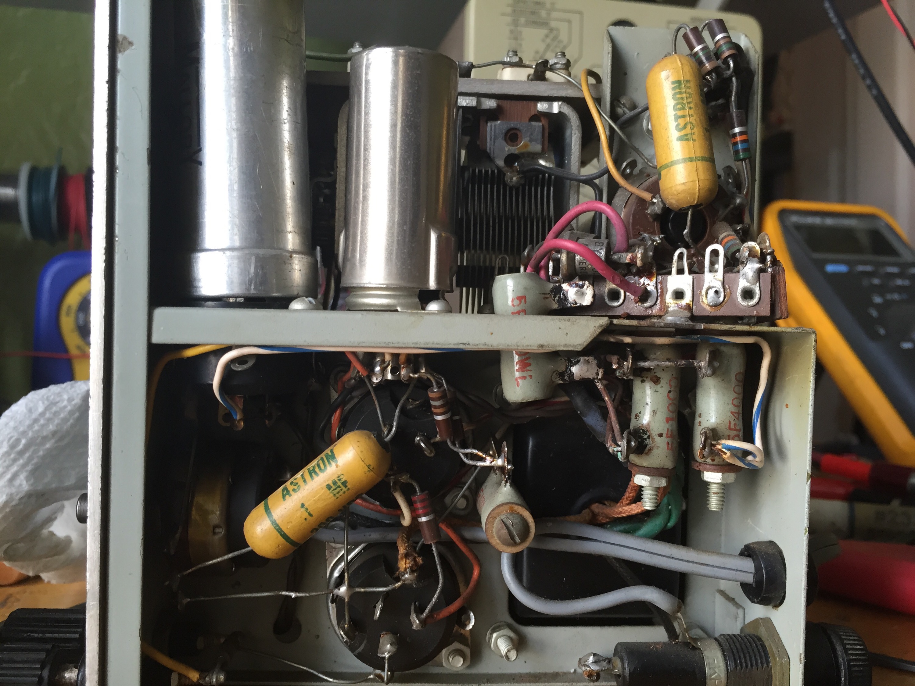
With the glass face out of the way, I figured I’d get a few good macro shots of the innards.  The white bobbin on the top is a resistor, while I believe the brass stock in the back is a shunt.

DSC_0137


Here’s a closer look at the wire wound resistor.  DSC_0146

And the super fine wire from the V+ connection
DSC_0145

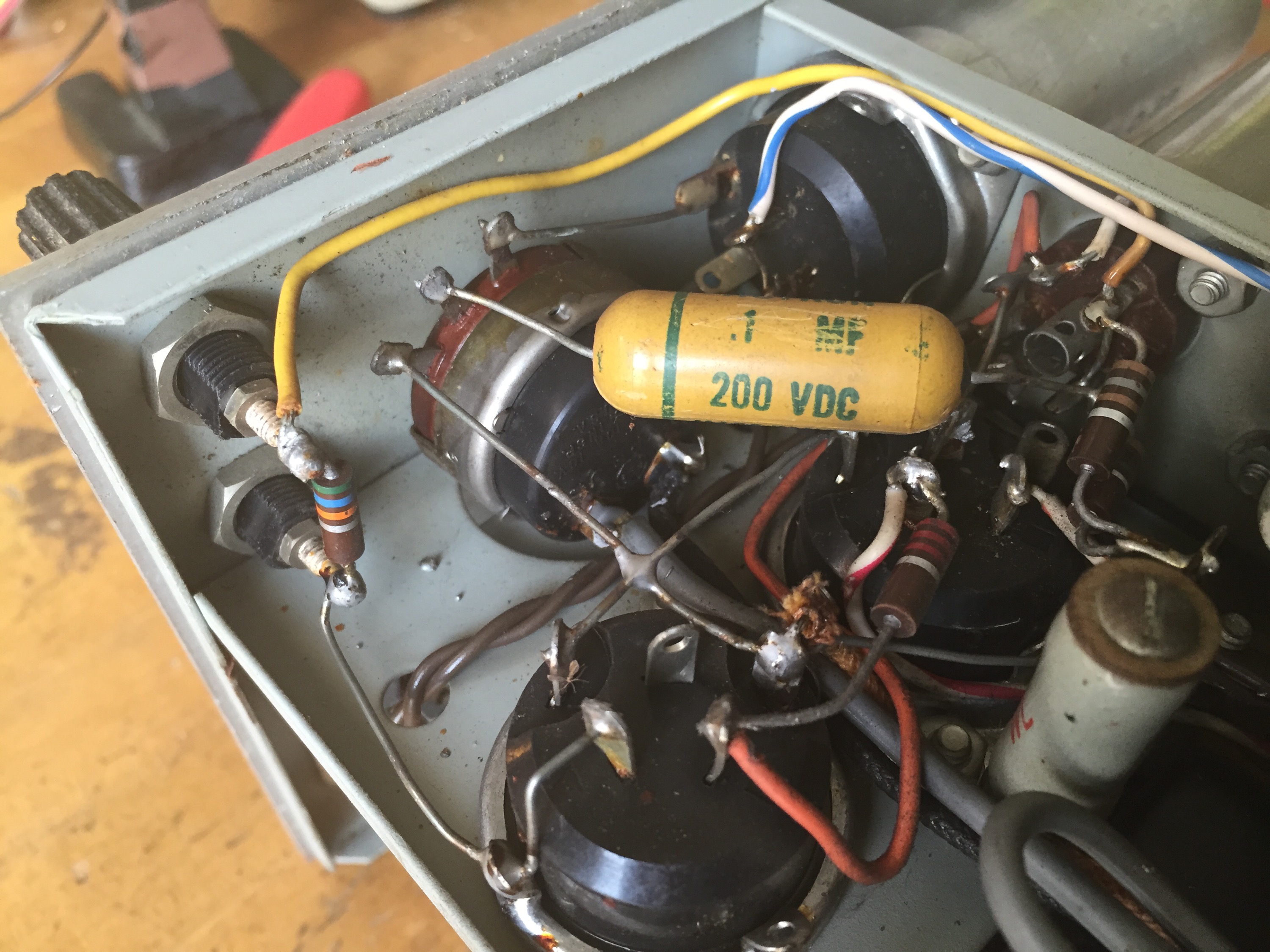
The way this meter is able to display wattage is by multiplying voltage by current.  It does this by way of nested coils:  one stationary and one on the movement.  Here is shown the meter at rest.
DSC_0143

here is the meter at half way, notice the inner bobbin is rotated.
DSC_0144


A few close-ups of the movement

DSC_0149

DSC_0151

DSC_0154


So then I re-installed the meter face and gave it a quick, damp wipe down.  Big Mistake.  See the streaks I’ve caused?  Sigh.. live and learn.  It was a stupid, ham-fisted move on my part.

DSC_0164

I also scratched up the glass a bit while I was removing the gasket from it’s face, but it’s not as noticeable  Here’s the finished product.  It seems to have a lot of momentum and/or friction to overcome, and as such doesn’t land on an accurate value when slowly incrementing the voltage.  I’ve only experimented with my 100w desk lamp, but it seems I can only get an accurate reading if I switch from off to full line voltage.  Alternately, it’s just out of cal (which seems odd, as there’s nothing to calibrate) and the over-swing just happens to land the needle on the right number.

DSC_0165

I took a picture with the meter against a ruler and some graph paper so I could recreate the next one.  Why I didn’t just trace it is beyond me.

IMG_4703.JPG

Continued adventures in nixie counting

Getting the Transistor Specialties 1519 back on the bench for some overdue continued exploration.

I’ve found that I can get the ‘B’ channel to increment it’s count by toggling the gate Start/Stop switch.  It’s a center return switch, and only by running the switch all the way from Stop to Start, across the center detent, can I get it to increment.

Some further discoveries:
this toggle trick only works around 110v line voltage.  I’m running it on a vairac, limiting it to 115v.
Earlier I think remarked that it was either 3 different flavors of boards, then I realized it might only be two?  It’s three.  The first counter card is different.  Though the layout is largely the same, some components are different, and it dawned on me only now that it’s probably because that card is the one’s counter, and thus needs to have a much higher bandwidth than those following it.  duh.

Here’s the beginnings of a schematic for the input card (one of two) ignore the ‘trigger level controls’ note.

TSI_1519_INPUT1

Variac on Steroids: Tektronix TU-75B

IMG_4651.JPGEvery bench needs a a good Variac.  Until I found this piece, my daily use variac was a 60’s era Radio Shack unit cobbled onto some ply with a JBox on the count of missing the original cord and socket.

IMG_4663.JPG

It works fine, though only rated for 5 amps and gets a little warm with loads well below that.

The Tektronix TU-75B was apparently designed and built primarily as an in-house device to aid in final testing & adjustment of scopes on their way out the door.  I’ve yet to find documentation on it, and the only other photos I’ve seen show similarly low serial numbers, so I suspect these weren’t made in large numbers.  When I saw it on eBay, I couldn’t resist.

The simplest of Variacs just have a knob to adjust the voltage.  Some of the nicer ones also have a voltmeter and/or ammeter.  This unit has a voltmeter, a wattmeter, and selectable ballasts, in the form of 3 light bulbs (more on this later)

There were a few problems noted in the listing, and a few that weren’t.  One meter is missing it’s glass, and the other’s glass is loose.  I’ve got tape on the wattmeter’s glass face to pull it forward and keep it from interfering with the needle.  I’m going to pick up some Permetex glass sealer for the job, which is also apparently what you should use to re-seat the glass envelope of tubes & CRTs in their socket bases.  I’m also going to laser cut some acrylic to replace the missing face.
IMG_4660.JPG

The voltmeter’s needle is a little bent up, but it seems to move OK.

IMG_4659.JPG

The other glaring error was that the brush on the variac wasn’t making contact with the winding.  Super simple fix:  I just had to loosen the rotor and move it closer on the shaft until the brush made contact.  Here it is after the fix. IMG_4657.JPG

There’s also a fuse holder, that appears to be a mod of some sort:IMG_4666.JPG

I like the spare fuse holder.  Note that the tektronix part numbers written in.  The knob that the fuses are connected is the wattmeter multiplier, which appears to be a very low resistance rheostat.  With this mod the knob not only controls the range of the meter, but which fuse is in-line.

I’m a little fuzzy on how the transformer is wired.  Perhaps it’s set up as a series of shunts for the wattmeter?  I’ll have to draw this all out if I can’t find a schematic.

Speaking of the wattmeter,  it’s a 4 terminal device, with separate connections for voltage & amperage, which I guess makes sense; if the voltage was constant, you could get away with just measuring the current, but since the voltage is variable, you have to take both into account.  So how does this meter work?  Does it mechanically multiply the two?  A gentleman on this post confirms my suspicion:

“If this is basically an analog meter using two coils to perform the required instantaneous multiplication, then the voltage coil is connected to the needle, moves, is a high resistance, and probably has a series resistor to scale the voltage, and the fixed coil that the moving coil interacts with is the current coil. If no external current transformer is used, then there is a basic current rating of the current coil relating to the full scale power rating of the meter.

See:
“Basic Electrical Measurements”, by Melville B Stout, 1950, Prentice-Hall.
Look up Indicating instruments – electrodynamometer movement – 418 – 423, and 442 – 450.

Interesting…

Looks like there was an… electrical incident at some point; the leads on the power switch have felt the wrath of some poor fellow’s mistake.  The connections appear to be solid, so I may just slowly back away.   I’d hate to disturb that beautiful wire-loom.

IMG_4655.JPG

When I snugged brush back up against the winding, the inner contacts (which is a brass pad pushing against a brass plate) make a horrible squeak.  I tried everything I could to eliminate this sound to no avail.  The squeak happens right around 90 – 110 volts, so I’ve rationalized this as an audible alarm that you’re approaching full line-voltage, which is actually quite handy.  Go Tektronix.

I’ll cover the ballasts in another post, but short answer: They’re light-bulbs that you can switch in in series to limit the current.  It’s an old trick, but nice to have it all built in one nice enclosure.

519 Graticule

Gallery

This gallery contains 5 photos.

Some quick shots of it lit up   Cranked up to full brightness for a few seconds, just to see the leading edge of the pulse.  Don’t do this for long or often.

Tektronix 519 Graticule

Today I finally got schooled on how to use the laser in the model shop.  Frau_Farbissina_laser

As mentioned in a previous post, I drew up the graticule for my Tektronix 519 as a DWG for this laser intro.

The basic workflow is:

  1. make a DWG, using colors to represent different laser attributes (power, speed)
  2. Power up the laser, and use bed Z control and spacer stick to focus
  3. open the file in AutoCAD Trueview(?)
  4. Print to laser driver, which opens up driver app
  5. load the medium
  6. assign colors to laser attributes
  7. drag the print file onto the print area
  8. a few other things
  9. hit go

We used 1/8″ clear cast acrylic.  I don’t remember what the cutting power was, but the engraving setting was power of 8, speed of 1.  Keeping the power the same & halving the speed would result in a deeper cut.

We made two, just for kicks, and they turned out pretty well


IMG_4358.JPG


With the paper removed
IMG_4359.JPG

Compared to the one from my 551
IMG_4362.JPG

Closeup
IMG_4361.JPG

the 551 graticule stacked on top of the freshly cut 519.  Just different enough to be annoying.IMG_4367.JPG

Here it is, installed
IMG_4366.JPG

Not bad for my first attempt.  I’m going to build a solid black aperture plate next.

Waveforms 510-B Oscillator

I picked this up at a HOSARC Hamfest two or three years ago for $20.  The guy said it mostly worked, and it indeed mostly did. IMG_4286.JPG

I had never heard of this company before, and searches on the internet don’t unearth too much detail.

The unit works fine up to the 3rd range setting, but the ‘X1KC’ & ‘X1MC’ ranges were temperamental to say the least.

Time to crack ‘er open:
IMG_4283.JPG

A very compact design for the era.
IMG_4292.JPG
major components:
(2) 6AK6
(1) SJ7
(3) dual 20uf @ 350 cans.
(2) diodes in the power supply (non-regulated)
(1) ballast lamp

It appears to be an RC Wien bridge oscillator, with precision resistors on the decade switch, and a dual bank variable capacitor for the frequency knob.  Also typical of the era is the incandescent lamp as a part of the oscillator feedback circuit.  Basically, the gain of an oscillator must be exactly one to sustain oscillation, but in order to initially achieve it, a gain of more than one is required. The incandescent lamp’s resistance increases as it heats up, so when used in the feedback circuit, the gain can start high, then level off at 1 as the lamp warms up.  Good explanation here.

Here’s the output level control / power switch
IMG_4288.JPG

I yanked the knobs for cleaningIMG_4291.JPG

Tubes were tested
IMG_4290.JPG

It starts to clean up nicely
IMG_4294.JPG

Tube shields cleaned with damp aluminum foil, acrylic pointer cleaned with detergent, and took the surface rust off the screw heads with a wire brush.IMG_4300.JPG
IMG_4295.JPG

As far as the last two bands, a thorough cleaning of the switch greatly improved the situation, though the highest scale still sometimes needs a little wiggle.  I suppose I could entirely remove the switch and give it a real cleaning…

It cleaned up OK:
IMG_4299.JPG


Here’s the output through my Heathkit HD-1 Harmonic distortion meter.  Channel one (on top) is the signal from the oscillator, Channel 2 is the output from the distortion meter.  This output is the difference between the original signal, and everything except an ideal version of the original signal; a better & more detailed explanation here (same site as the previous link – good resource!)
My dumbed down version – this output shows where, in which direction, and by how much, the signal is incorrect; it basically points out where your waveform sucks.  An ideal sinewave would show as a straight line on the output of a properly tuned HD-1.  IMG_4301.JPG

In contrast, here’s the same setup with my Heathkit AG-9
IMG_4304.JPG

though timebase is different, the amplitude ratio is the same; the AG-9 blows this Oscillator out of the water.
Manual en route, stay tuned for more.

UPDATE 8/4:
Manual posted here

good page from a fellow boat anchor aficionado

‘Boat Anchor’ is an affectionate term used to refer to old tube gear, primarily radios and test equipment.

This guy has a great site dedicated to his collection & adventures in restoration.  I didn’t see any Tektronix gear, but hey, no one’s perfect.

Speaking of boat anchors, I stumbled across this site that attempts to humorously quantify the relative beauty of these old relics:
BABE (boat anchor beauty evaluation)

519 CRT bezel

My 519 is generally in immaculate condition, however it’s missing it’s original bezel.  It came with what appears to be a standard 500 series bezel, and some aluminum knurled knobs keeping it loosely attached.

I think there were two versions of the original bezel assembly, one with a camera attachment, one without.  Tim Koeth’s appears to have a the camera attachment (chronicled here), while the one I saw at Skycraft did not.  Check out this shot of his collection – he just may have me out oscilloscope’d.  Here’s the shot of the one at Skycraft:
IMG_4019

What’s interesting about this one is that the entries for serial, sensitivity, and risetime appear to be blank.  A few things to note about the 519 and it’s CRT:

  • There is no vertical amplifier.  The signal is passed directly to the distributed vertical deflection plates.
  • The CRT & shield are typically paired, in part to help protect the CRT.
  • The vertical sensitivity and risetime is individually characterized for each CRT at the factory, and is marked on the shield and faceplate.  They’re typically on the order of 10v per cm and 350ps, respectively.
  • The sensitivity and risetime are marked on the backlit faceplate such that it’s incorporated into photographs, like this
  • Because of the extreme speeds that this device operates on, the usable area of the CRT is comparatively tiny; 6cm x 2cm.  Compare that with other scopes of the time, which had an active areas of 10cm x 4cm, or 10cm x 6cm.

A little more on that last point.  In order to capture extremely fast events in real time,  you have to sweep the beam across the screen very quickly.  The quicker the beam scans across the screen, the less time the beam spends at any given point, and thus the less energy is imparted onto the phosphor.  To get enough energy on to the phosphor to make it glow visibly at these speeds requires tremendous accelerating voltages; 24,000 volts(!) in the case of this scope.  The trouble is, the more energy an electron beam has, the harder it is to move it around.  This is why the 519 ended up being a 100 lb beast, with sweep generator is driven by a forced-air cooled RF transmitter tube, a relatively dreadful vertical sensitivity, and a minuscule viewable area.   Another thing to keep in mind is that while repetitive signals keep sweeping across the CRT face, continuously refreshing the image, this was made to capture single shot events on camera (such as nuclear events), so the beam had to be bright enough to register on film on a single pass lasting less than 50 billionths of a second.

Back to my scope.  Here’s what it looks like with the bezel removed
IMG_3914.JPG

For kicks, I tried installing the graticule from my 551.
IMG_3916.JPG
That’s not just parallax.  The graticule illumination lamps and the notches on the plexi sheet don’t line up.
IMG_3917.JPG

Remember, this was bespoke machine, only loosely based on the 500 series standards of the time.

Upon closer examination of the CRT shield, I noticed mine is sadly lacking the sticker that proclaims the sensitivity and risetime.
IMG_3910.JPG
Other examples chronicled have a second sticker above this one with hand marked sensitivity & risetime.  I really don’t have the courage to pull the CRT from it’s shield to hunt for any other markings.

I went ahead and drew up a graticule that should fit:
tek919 bezel

This’ll make it’s way to the laser next week when I’m back in town. Stay tuned!

Skycraft!

On my way home from InfoComm, I had a chance to visit what I would highly recommend as a pilgrimage to any geek,  Skycraft Surplus.
IMG_4008

I didn’t snap too many photos, since I thought it seemed rude, but here’s a few:

Would you believe a Tektronix 519 was staring me down as I walked in the door?
IMG_4009
Sadly, not for sale (on second thought, maybe that’s for the best).  Serial # 000729.

Who wouldn’t want one of these?!?
IMG_4010

Isles and isles of hardware, fasteners, fittings, switches, passive & active components.  Drawers full of any little bolt, nut, washer, or standoff you can imagine, in a variety of materials.
IMG_4013

I need one of these for my Meth Lab.
IMG_4014

Don’t forget to look up
IMG_4017 IMG_4016

Somehow, I walked out of here spending less than $50, probably because none of these would fit in my carry-on.
IMG_4011

Need wire?
IMG_4015

This is about a third of their stock.  I ended up picking up a few 50′ coils of some nice silicone jacketed hook-up wire, great for patch-cords.

And finally, I snapped a few close-ups of the 519’s bezel, since mine doesn’t have one, and I’m attempting to recreate it
IMG_4019 IMG_4021

More on that effort in another post.