The Tektronix 519

So I got a 519.

IMG_3526

Here it is in a rather compromising position,  getting its caps checked.

“Turn your head and cough”IMG_3494.JPG

What’s a Tektronix 519?  Arguably the biggest, baddest, ballsiest oscilloscope ever fucking made.  Designed over 50 years ago, and built in extremely limited numbers through the 60s and early 70s, it was unsurpassed in its ability to capture extremely fast, transient or one-shot events, as well as repetitive signals of up to 1GHz,  in real time.

It is a machine unlike anything Tektronix had ever made, and due to the fact that it was the pet project of a senior engineer working free from the boundaries of the institution’s design team, it bared a only casual resemblance to the rest of their line-up.

Because the variac I have easy access to is only good for 5 amps or so (and gets a bit toasty at that),  I decided to just go for it, and hit it with full mains voltage.  Side note: I really need to get that 20A variac out of storage and wired up.  Nothing.

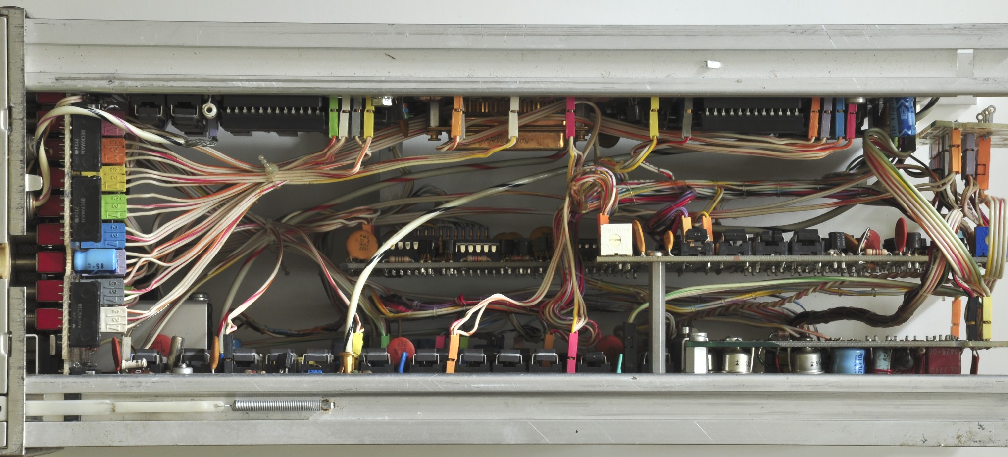
Checked the fuse, and there was a blown 4 amp slo-blow. Based on the markings, a 4 amp fuse suggests that the unit was being used at 240v, otherwise it would have had a 7 amp fuse for 120v  operation.  I carefully rolled the unit over to remove the bottom panel and expose the transformer wiring.  To my surprise, the transformer was wired for 120v operation.  I’m just preying no one tried to power this thing up on 240v, but I suspect not.  With the exception of a fine layer of dust, the interior is immaculate, and shows no signs of distressed components.  I’m also pretty sure I heard a brief ‘chunk’ of the blower try to start over the heavy click of the switch, so it is possible that it was I who blew the incorrectly installed fuse.

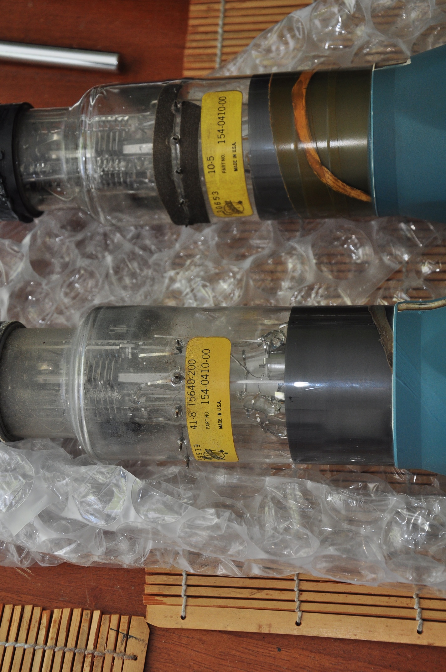
I’m taking this as a sign that I should do a more thorough inspection before firing this thing up for the first time in god only knows how many years.  With the chassis still rolled over (I would like to move this heavy, fragile, priceless relic as little as possible!), I went to work testing the supply caps who’s terminals are accessed on the underside of the chassis.  These are the ‘low voltage’ supplies, covering about 10 different ranges between -250v through +650v.  The high voltage supplies are -4,100v and +20,000v (!!).

Here’s my updated test & reforming rig.  My heathkit IT-28 capacitor checker, my trusty old Fluke 83 for measuring voltage across the cap, and a Bell & Howell multimeter for measuring current.  This is a kludge to say the least, but it’s what I had on hand.  A programmable, high voltage power supply tailored for cap reforming sounds like an interesting next project.  In the mean time,  this will have to do.

tek519testing

Here’s a closeup showing the charge line from the calibration step generator.  It’s in the way and making it difficult to disconnect the caps, lets see if we can remove it. IMG_3530.JPG

Removing the screws in the GR-874 connector…

IMG_3532.JPG

And loosening the clamps on the charge line…

IMG_3531.JPG IMG_3533.JPG

…let me carefully pull the charge line out through the front panel.

Here it is on my bench with its outer sleeve removed.IMG_3534.JPG

Here’s the coil that wraps around the charge line and triggers the reed relay within it.  It’s also worth noting that the bit of corrosion seen in the photo below represents the only bit of it I’ve found anywhere in here so far.IMG_3536.JPG

I started with C613, then moved on to C661,2,3, which is three 125uf caps in parallel.  I left the cap fully in-circuit for some of my early tests.

Once I disconnect the + side of the cap,  I connect the reforming circuit and start out at 50v and slowly work up to the rated voltage of the cap.  As the voltage increases,  it takes longer for the current to drop to an acceptable level.  As far as what is considered acceptable leakage current,  I’ve read a variety of opinions.  This site has a handy chart, which suggests that anything under a few mA is acceptable for these beastly 125uf, 450v caps.  I’ll move on to the next higher voltage when the leakage current drops below a mA,  then hold at the rated voltage until the current levels off.  So far, that’s been on the order of a few hundred uA, which is great for 45+ year old caps.

Ready for smoke testIMG_3545.JPG

so is Fire ChickenIMG_3546.JPG

YEAHHHH!IMG_3549.JPG

I was dorky enough to record a video.  Here it is in all of it’s dark, shaky, glory.  Pardon the occasional explicative, I was very excited.

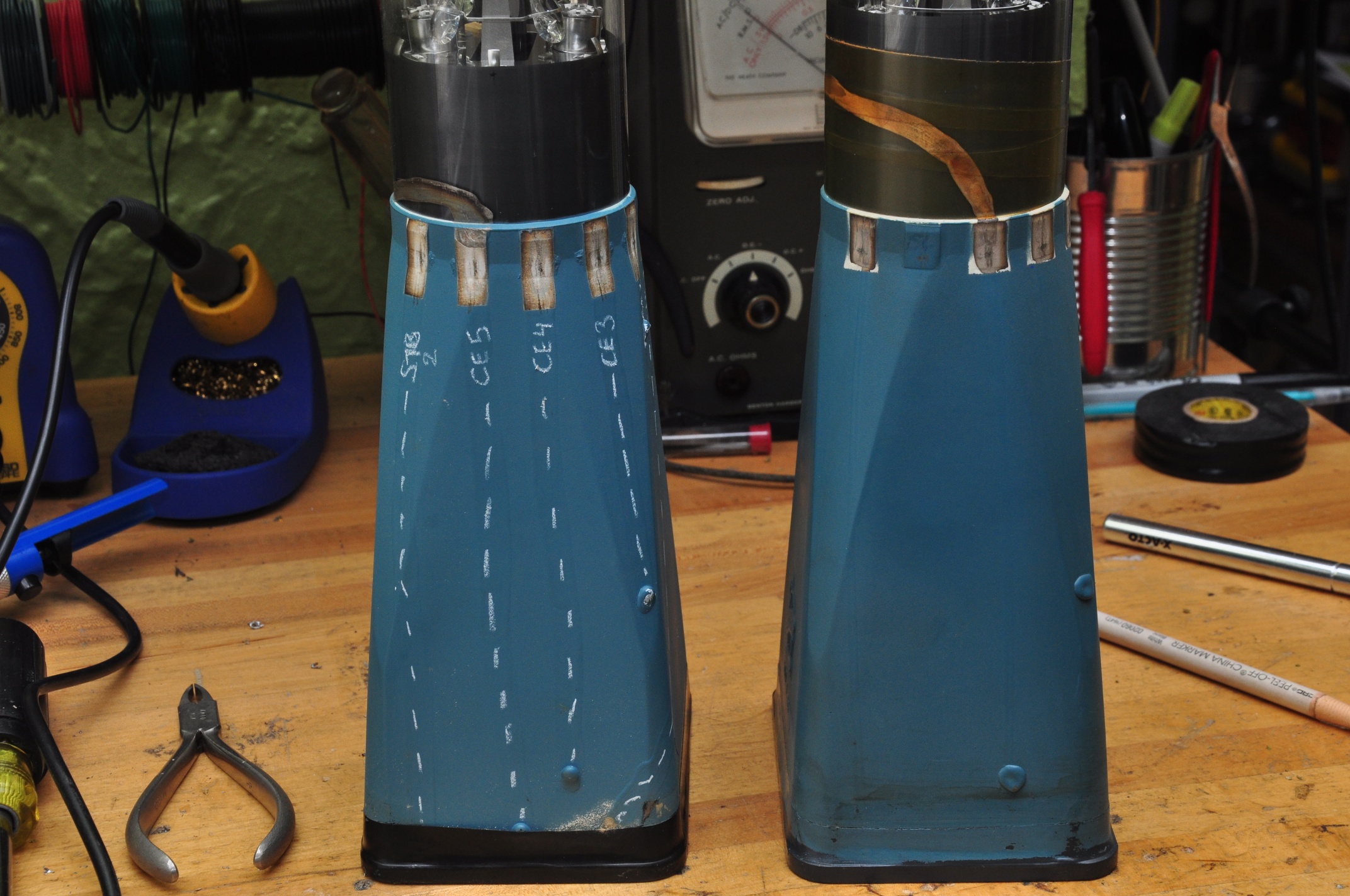
I was able to get a free running trace, at all but one sweep speed.  The trace was crisp, and I was able to move it as expected via the positioning controls.  It is a shade of blue that I have never seen on a scope CRT before (P11 phosphor).  The 24kV accelerating potential made for a staticy, zappy sound when the relay kicked in to power the ‘low’ and high voltage supplies.

I hooked up the rate generator to the input.  While increasing the multiplier control, I heard a snap, and saw a white glow in V717, a 77http://paulcarbone.com/blog/wp-admin/post.php?post=409&action=edit34/6GE8 which is part of the +450V supply.  This I believe is completely unrelated, but obviously worth investigating.

Next Steps:

  1. Check V717 in my tube tester
  2. Check the output of the Rate Generator & Step generator with either my 7834, or my 661 (heheheee).
  3. See if I can get it to trigger on anything.

V717 is a 7734/6GE8, a combo triode + pentode.  What claims to be the latest settings sheet for my Heathkit TT-1 tube tester does not have this tube.  This is the second time that’s happened this month, and it’s starting to chap my ass.  I have a few other testers that are in need of resurrection, but I thought that the TT-1 was the most comprehensive.  I’ll have to double check next time I’m back up at ‘The House for Wayward Oscilloscopes’.  grrr….  Lets just put it back in and check the 450v line.  Perhaps this transient event I witnessed was not actually damaging to the tube.

Here’s the output of the Rate Generator on my 7603IMG_3552.JPG

With Function set to ‘Sync’, I was able to get this trace at 50nS / cm.  Very sporadic and required constant fiddling with the sync & vernier controls.
IMG_3553.JPG

After some more fiddling, I was able to get this trace at 10nS.  20nS is the one that doesn’t work.
IMG_3558.JPG
That’s insane.  I’ve never seen a trace that sharp before.  This thing is a monster.

7D01 Teardown

-IN PROGRESS POST-

DSC_0774

As I’ve previously mentioned, I’m in possession of no less then three, complete, working 7D01+ Display Formatter pairs (2 DF01s & 1DF02).  I got my original one working, keeping one as a maintenance spare / parts unit, and tearing down & stripping the final one.

It did take a moment of inward reflection before I decided to sacrifice a Tektronix product, but I decided:

  • It’s not particularly rare;  You’ll always see one or two on eBay.  Though they’re asking price is usually upwards of $200 (or sometimes more, which is just silly), they really only sell for about $50 – $100.  They were made from 1977 to 1985, though I don’t know how many were actually made.
  • It’s been an interesting circuit to get to know, and further poking will be educational.
  • It’s a trove of useful parts, including a beautiful ceramic & gold MC6800 CPU in the DF01, 20+ really nice toggle switches, tons of discrete logic, a dual concentric encoder, and some dual concentric pots.  I’ve already made a rudimentary 1Mhz clock circuit using some of it’s parts.
  • It’ll be fun, and I’ll take some pictures for here and the wiki.
  • Did I mention I have three of them?

The front panel circuit board is called out as the recognizer & trigger selector.  It also has the differential line receivers (Motorola MC10216) which are the input buffers for the P6451 probes.  The probes connect via 2 25-pin micro sub-D connectors.


7834 Readout repairs, continued


After my previous antics with the 7834 readout system, the outcome was:

  • U3401 Zeros logic & memory – tek part 155-0018 – the original culprit.  Replaced with one from ebay.
  • U3418 Column decoder –  tek part 155-0014, which I think I killed during repairs. Replaced with one from ebay.
  • U3477 7402 quad 2 input NOR gate – smoked during repairs.  Replaced with a 74ALS02 from stock.
  • It turned out U3232, the row data switch that cycles through the 8 plugin display channels was bad as well,  botching the readout in horizontal A bottom, and horizontal B top & bottom.   Replacement sourced from ebay.

So far, I’ve spent $50 on the scope, and another $50 or so on replacement chips.  Still not bad at all.

Here’s a few shots using the 7B85’s delta time feature, which lets you do fun things like measure frequency, rise-time, and pulse-width directly using the on-screen delay time read-out.  Thanks to Peter on the TekWiki who’s entry on the 7B85 pointed out these features.

These photos are of a rudimentary clock circuit I made using parts from the DF01

FullSizeRender FullSizeRender-1

Tek 453

IMG_3520

This was actually the first scope I got as “an Adult”.  I think I paid about $100 for it about 6 years ago.  Since then, it’s been my daily use scope, since it fits atop a rolling art-cart under my bench.

Everything works great, except the B sweep only triggers on ‘starts after delay’, not ‘triggerable after delay’, which means there’s something fishy towards the front end of the B trigger circuit.

Great write-up of 454 triggering diagnosis here. Punch-line: it was the tunnel-diode.

Also suspected Nuvistor v633, type 8393.  Substitution with a claimed-good tube didn’t change the issue, so I’m suspecting it less, but unfortunately I can’t locate the test parameters for the the 8393.
Found it for the 6cw4 (same pin-out?)
Tube    Plate  Bias   Fil.    Meter   Sig.     Selectors                 R.P.       Remarks
6CW4  C        7L     6.3   32        4         03050-0010-706    1430      Tr;X4.

Boom – An 8393 is a 7586 w/ a 13.5v filament.  So, for the TT-1:
Tube    Plate  Bias   Fil.    Meter   Sig.     Selectors                 R.P.       Remarks
8393  O        7L     12   36        4         03050-0010-706    1140      Tr;X4.

UPDATE 5/3: Everything around that Nuvistor seems OK, but nothing is coming out of it, with either the original or replacement.  They both test dead.  So either:
1) I’m testing them wrong, and it’s something else in the circuit, or
2) I have two bad 8393s.
replacements en route, 3 for $45.  Damn these things are getting expensive.

I also realized that this Nuvistor is a part of the signal chain when in XY mode, which I could never get working.

UPDATE 5/8: Replacing v633 Nuvistor fixed the X/Y mode, but ‘B’ is still not triggering on it’s own, so there’s still some drama in the triggering circuit.


Tektronix 564 CRT Replacement

I figured it was time to break this off into it’s own post.  After some initial troubleshooting, I’d determined that the CRT was the source of the intensity and focus flickering I was experiencing.
I ordered a replacement I found on eBay, and it arrived yesterday, safely and extremely well packed:  Here it is after unbubblewrapping:
DSC_0207

I proceeded to carefully disconnect and remove the old CRT, leaving a gaping hole in the business end of the scope:
DSC_0224
Note the electrode connectors that press against pads on the neck of the CRT.  in front of that is the trace rotation coil, wrapped around a black plastic bobbin.

I compared the two to make sure they were in fact identical.  Spoiler alert:  They’re not.  The part# is the same, but there are other markings that differ.
DSC_0231

OK though, same part number, we should be good, right?  Hmm.. one of these things is not like the other: DSC_0236
There are 6 pads around the old CRT, and 6 corresponding contacts on the scope.  The new screen is missing the 2nd (or 5th?) pad.  Additionally, it looks like there’s a conductive trace coming out of the left of the 2nd pad on the old CRT that’s attached to the 3rd trace on the new one.  I needed to do a little more investigation before I was comfortable just shoving in the new screen and hoping for the best.

These connections are all a part of the storage circuitry, as seen in the schematic below.

Tek564Storage

After a bit of cold metering in the scope, I was able to determine which connections were which on the CRT, and I marked them with a grease pencil:
DSC_0240

So pins 1 & 6 (counting counterclockwise from the bottom in the scope) are STR1 & STR2, the upper and lower storage targets, while 2 – 5 are CE1 – CE5, the collimation electrodes.  I’ve marked the path of the conductive traces so they’re more visible,  you can see that they each terminate at the connection to their respective grids.

So the new replacement is just missing the last collimation electrode.  That doesn’t seem like such a big deal.  Maybe they realized it just wasn’t needed it in subsequent revisions?   The original has the ‘T5640-200’ in it’s markings, which matches the description in the manual from BAMA (©1964), but the replacement does not.  The replacement has what appears to be a lower serial number, but I’d be surprised if it was the older one;  It seems more likely that they removed an electrode in later models than leaving the space and adding one later.  Build techniques also differ.  The traces and connections on the replacement are finer and cleaner, but I don’t know if that equates to a earlier, smaller, more hand-built batch, or a later, more refined manufacturing process.  Any insight would be greatly appreciated.

DSC_0246

Feeling confident enough, I carefully installed the new CRT and brought it up slowly on the variac.  I got a beautifully sharp trace that didn’t flinch, even with gentle taps on the tube:
DSC_0257

As you can see, intensified mode works great.

One of my other recent purchases was a Heathkit TT-1 Tube tester.  I started out the previous version diagnosing a smoking resistor in the storage section power supply.  Now I had a way to check the tube.  Both sides of the 12AT7 checked out OK on mutual conductance and shorts, but one side failed the grid current test (exhibiting lots of it).  AH HA!!

I suspect the grid current was causing excessive draw on the 475v supply, which is why the resistor was overheating.  I replaced the tube and slowly brought it up on the variac –  low and behold the resistor remained cool.
Wait a minute,  a 12AT7?  The schematic (and nicely silkscreened chassis) calls for a 12AU7.  Huh,  I didn’t realize that upon first inspection.  The 12AT7 has a much higher gain then the 12AU7, and I wonder if that led to the premature failure of the tube.  It now has the correct tube.

Next on the hitlist:

  • Documenting the storage functionality.  It sort of works, but needs some attention
  • Understanding the grid current test on the TT-1
  • Sourcing a replacement handle.  I actually don’t mind going off-brand here, and would dig a custom replacement as long as it made use of the original mounting hardware.


Tektronix 564

DSC_0004

Picked this up as a part of a larger lot, and was the first I attempted to power up.  I did so stupidly, without a Variac.  Quickly shut down after smelling smoke from R646, a 100Ω 1W resistor that’s a part of the unregulated 475v line.  Metered it after the incident, and it appears to be OK.

Yanked the plugins and grabbed my newly re-wired Variac.  as I rounded 50v, things started to spring to life – around 80v I got a spot on the CRT, and R646 was HOT.  Shut ‘er down.

I think I’m going to yank all the tubes & transistors in the power supply, and check each supply one at a time, starting with the -100v supply.  We start with the -100v because as with most Tek scopes of the era,  the -100v (or -150v) supply was the one that all other supplies were referenced from.  We’ll start with -100v, then +125v, then +300v.  While the 475v supply is unregulated, it comes into close contact with some of the other supplies around the storage circuitry, which is also on the list of suspects.  Just for a chuckle, remember all of these are considered ‘low voltage’ supplies 😉

Pulled the following:
V667     6AS7     +300/150v supply
V674     6AU6     +300v supply
V654     6AU6     +150v supply
V800     6CZ5     -3kv supply
V814     12BH7    -3kv supply
V913     12AU7     storage

With only the tubes in the -100v supply installed, I get -150v on the rail when line voltage is brought up to 115v.  There’s about 90v across the gas regular tube instead of 80v.  I’m not sure if this is because the 125v supply isn’t up?  Furthermore, what’s with the pin 6 connection on the regulator tube?

With V667, V674 & V654 reinstalled, I can get the -100v power supply dialed into -100.0v.

Attempted to dial in the +125v supply but it jumps between 123.7v & 126v as I adjust the pot. 125.9v was as close as I could get it.  Getting the +300v rail dialed in was no problem, same with the -12.2v supply.

420v unregulated reads 427v, 475v unregulated reads 485v with 115v line voltage.

Now I’m suspecting the problem is in the storage circuitry, since that appears to be the only thing powered from the 475v supply.  As a side note, are these tin whiskers?

DSC_0007

OK, with V800 & V814 installed, I get a spot on the CRT!  Focus & astig controls change the spot shape, and location on the screen.  When I get it as sharp as I can, the intensity control also makes the beam move around.  Lets try a horizontal plugin.

DSC_0010

SUCCESS!  Lets try the vertical plug-in.

DSC_0014

It needs a cal and cleaning, but all 4 traces seem to work somewhat.  Even the delayed sweep seems to work:DSC_0015

So the trouble is in the storage circuitry.

After running for a while, the intensity started to jump around, became very bright, and the intensity control no longer functioned.  Stay tuned for more…

10/12 UPDATE

it’s general intermittent intensity issues, stemming somewhere from the HV supply.

C830 & C832 measured around .0026u which correlates to the parts list, but not the schematic, which calls them out at .0068u

R842 ((2)2.7M+(2)3.3=12M) Measured 13M cold, measured open after about 15min operation, then slowly dropped the meter picked it up around 50M, and it’s almost all the way back down.  Some metering in the early minutes after shutdown leads me to suspect one of the 3.3M resistors.

there’s a strong mechanical component to the problem; lightly pressing on the HV portion of the central chassis would drastically affect the intensity of the trace.

metering across the two neon bulbs I’d see anywhere between 50v & 120v that’s directly affected by the intensity control.  In one flicker scenario, the intensity wavers but this voltage remains consistent.  After being warmed up for about 20 min, the flickering would affect this voltage, causing the neon lights to fire

11/1 UPDATE:
I was wrong about the resistors, they read OK when immediately lifted from the circuit after power-down.
I’ve measured the HV supplies, and they seem consistent during the focus & intensity flickering, though measuring them does affect the trace (which I was surprised would happen with a 75MΩ probe impedance).
Screen voltage of V800 is around 65v for a normal trace at .2ms and can jump as high as 90v during a full bloom event.

As per the recommendation of Albert on the forum, I checked the V800 screen w/o the CRT connected, and it was around 65v.
Gently tapping on the chassis above the HV terminal strip does accentuate the issue, but I can’t find a component (either tube or passive) that responds specifically to some more directed tapping. I’ve re-seated the CRT socket, but it seems those wires are particularly sensitive to giggling. I opened up the the socket, and the pins look good.

It turns out tapping directly on the CRT shield or neck causes the biggest change in intensity, so now I’m fearing it’s a mechanical problem with the CRT.  I can wiggle the CRT or leads to get a good trace, but it quickly goes back to incessant flickering.  This is getting really frusturating.  I think the only fix might be:
1) Sourcing a new CRT
2) Hitting it with a brick until I feel better

UPDATE:  There’s a replacement CRT en route, part # 154-0410-00  (P31 phosphor, same as mine).
CRT replacement chronicled here

Tektronix 7834 Mainframe readout repairs

DSC_1001(attempted) Repair log continues below

Picked this up about a year ago, and used it solely with my then slightly misbehaving 7D01, in combination with the DF01 Display Formatter.  Because the DF01 was gen’ing all the characters, I never noticed that the readout feature was misbehaving until I went to use a pair of conventional plugins.

7834 readout

There’s a few things wrong with this:
1) The characters are incorrect
2) The top and bottom of the vertical plugin readout are supposed to be for channels 1 and 2 respectively, but they both seem to respond to channel 1 only.

Regarding the incorrect characters, it appears that from this table, the characters are shifted one to the left of what they should be. ‘0S’ should read ‘1V’, and ‘4m’ should read ‘5u’  Columns and rows are selected by way of a current loop between the plug-in and mainframe, using .1ma steps between 0 & .9ma.

Oh, hello:
rowmatch

“Score!” I thought,  but sadly turning it does nothing.  Also, my columns are the issue, not the rows.  UPDATE – Column Match doesn’t do anything either.

So I started poking around with my 7D20 and found something strange coming out of the U3433, the custom timer chip:7834 readout board

Note the often overlooked screen annotation feature on the earlier 7k scopes 😉

So there should be a negative going pulse on pin 16 that corresponds to the waveform on pin 10.  Also note that negative portion of the waveform on page 10 are shorter where the pin 10 pulse is missing.  I went ahead and ordered a replacement U3433, we’ll see if that does anything.  In the mean time, I’m off to the tek message board…

09/16 UPDATE:
Heard back form a gentleman on the forum:
1) What I’m seeing on the output of U3433 is not uncommon and due to display skip (which is described in the manual, I just have to wrap my head around it)
2)  He recommended swapping U3429 row decoder & U3418 column decoder – did that, no change.
3) He recommended swapping U3232 row data switch and U3263 column data switch.  oh fuck, those are BURIED.  Standby for some fun.

9/16 UPDATE:
The power supply slides right out, making U3232 & U3263 accessible.  Well played Tektronix.   Swapping them made no change.

Here’s the bottom of the scope – note the plastic rails on the bottom of the PS on the left.  One of those was loose and keeping the PS from sliding out.  Had to pop the bottom cover off to free it.
DSC_0989

DSC_0992

resocketing a few of the transistors fixed the missing readouts on the left horizontal bay, and the upper/lower duplication I was seeing.  Now every bay has it’s readout, it’s just wrong.

9/17 UPDATE:
what’s supposed to be +4.4v on pin 9 into column decoder U3418 is only +3.84v
what’s supposed to be +14.5v on pin 10 is 14.8v

9/19 UPDATE:
Well, this has suddenly turned into a larger problem.  Yesterday I’d gotten some of the characters to change by paralleling in a decade substitution box.  Today I tried again but paralleled the wrong resistor (R3418), and I as was trying to pull the lead (live – dumb) I shorted something, heard a snap from the power supply, and the display went crazy, then dark.  I shut it down, and when I started it back up, U3447 started to release it’s magic smoke.
I can only suspect that one of the legs of the power supply has gone awry, but the power supply wont fire up when not under load.  I’m at a complete loss as to what to do next…

OK – moving on from despair…
With the readout board fully disconnected, the scope powers up and behaves normally (sans readout).  IMPORTANT NOTE:  When disconnecting the mini coax connectors, note that some of them have shield potentials of 15v, so take care to make sure they don’t touch the chassis.

9/20 UPDATE:
It was U3401 – zeros logic & memory.
I decided to swap out one chip at a time from the 7834 to the known good 7603, in order to asses the damage.  When I got to U3401, the same problem showed up on the 7603.  Total facepalm for not doing that earlier.  All other chips were OK, with the exception of U3418, the column decoder.  So now I’m down:
U3418 Column decoder –  tek part 155-0014
U3401 Zeros logic & memory – tek part 155-0018
U3477 7402 quad 2 input NOR gate – I only have an 74ALS02, not sure if that’ll cut it.

Replacements for U3418 & U3401 en route

9/20 UPDATE:
74ALS02 is fine for U3477, tried it in the 7603 (thanks David)

In retrospect, I should have suspected U3401 given that ‘>’ worked but ‘IDENTIFY’ didn’t, since it’s U3401 that signals the column & row data switches to run through the sequence of characters to spell ‘IDENTIFY’.

9/25 UPDATE:
After an in situ check of components around the affected areas, I pulled U3418 & U3401 from the 7603 and installed them in the 7834, held my breath, and power’d it up.  All good.  The soon-to-arrive replacements will make the 7603 whole again, though for now it doesn’t really matter, since it’s really only host to my 7D20 & 7D01.


Tekronix 7D01 Logic Analyzer


I took the red pill. IMG_2269

DSC_0535

Behold the Tektronix 7D01, first released in 1977, shown here with it’s companion display formatter.  As a side note, I really need a better lens.  This pin-cushioning is just too much.  105mm or 200mm prime macro (or micro as Nikon calls them) is high on the list.

This wasn’t Tektronix’s first bench-top logic device, but it was the first to have a tiny bit of smarts to it.

  • In 1975 they released the 821 4 bit word recognizer released in 1975.  Yep, a 4 whole bits.
  • In 1976 they released the LA501 as a part of the TM500 series instruments.  It could store up to 16 channels x 256 bits, and relied on an external display.  No word recognizer, no cursor, no read-out, just a simple timing diagram.

Hewlett Packard had a jump on the bench-top logic analysis tools, starting in 1973 with the 5000A logic state analyzer.  It’s no WOPR, but a respectable display of blinking lights nonetheless.

hp5000anim

By 1975, they had released several bench-top products.  The HP Memory project has a great page on the topic.

Back to the 7D01.   I’d picked it up a few months ago, and separately picked up one of the two 8 channel probes.  The probe connections are to the left of the word recognizer.  Note most logic analyzers are useless without their probes, and the probes are usually specific to one product or product family.  You can pick up this and other 80’s era logic gear for under $100, but be prepared to spend a comparable amount on a set of probes.

So I started mucking about with it, generating test sequences from an Arduino and learning out how to operate the thing, and saw a variety of intermittent failures:

Here’s the character generator on the display formatter losing it’s mind:
DSC_0092

Some extreme jitter in the display of the timing diagram:
DSC_0099

Here’s a quick video of one failure mode, this time with the display formatter removed.  Notice the characters look different, more on this later.

And here’s one more of the display formatter losing it’s mind in state table mode, filling every unused character slot with a ‘1’.
DSC_0334


The thing is,  I am now in possession of no less then three of these units, as I was given two ‘for parts’ when I picked up the 7603 & 7D20 a few weeks back.  And of course, these units both worked flawlessly.  I contemplated just calling my original unit the ‘parts’ spare, but that seemed like a cop-out, so I went forward attempting to repair my original, knowing I had an ample supply of parts, should they be needed.  Besides, that’s the real fun anyway.

I studied the manual during my daily subway commute the week prior to attempting to diagnose and repair.  Putting the display formatter issues aside, I suspected the counter on the cursor board was responsible for the racing numbers in the video, and that something was wonky with the flag signal which could explain the display blanking.

When confronted with a multitude of seemingly unpredictable problems such as these,  the best approach is often ‘take it apart and put it back together’, making sure to take pictures along the way to help in the reassembling effort.  This isn’t just the physical equivalent of ‘have you tried turning it on and off again?’;  Close visual inspection can reveal failed components, and re-seating 35+ year old connections can often fix intermittent problems.  Besides, without plug-in extenders which would let me probe around on the live-plugin running outside the mainframe, there really wasn’t much else I could do.

Left Side w/ Display Formatter removed.  The D-sub connector toward the back is where the Display Formatter connects. DSC_0434

Right Side, showing the two delay lines:
DSC_0437

Top View, after removing the back plate:
DSC_0458

The rear with the backplate off, before any further disassembly. DSC_0450

Removal of the edge connector card:  DSC_0459

The card removed, shown from the other side:
DSC_0468

Disassembly continues:
DSC_0476

Cursor board removed:
DSC_0478

The same board backlit:
DSC_0500

Memory board removed.  Tremble in awe at 512 BYTES of Static RAM. (arranged as 16x 256 bit chips).
DSC_0491

Dear god what have I done:
DSC_0495

As you can see, it wasn’t a total teardown.  I left the output board and word recognizer in place, as I could now reach and re-seat all of their connections and chips.

I didn’t individually pull and re-seat every chip, but I did give them all a firm press, and found that many had worked themselves loose.  All that SRAM and discrete logic really cooks, so it’s not surprising to see failure modes change as the unit warms up and pins move slightly as they heat up and expand.

It took another hour or two to get the whole thing back together.  While I took a bunch of photos (more then shown here), I still had a few stray wires that I needed to hunt down in the manual to figure out where they reconnected.  It helps that the wire harnesses are pre-bent and just the right length, so often times it’s obvious where to connect; however that also means there’s little to no slack, so there’s really only one way to route each wire.  I had a few runs that I had to re-snake through after I realized I’d taken the wrong path.
After one more visual check, I slid the plugin back into the 7603 mainframe, held my breath, and pulled the power button (it’s a strange power button).

WHEW.  Works like a charm.DSC_0503

Here it is a little while later, after I reattached the Display Formatter (DF01).

IMG_2273

Notice the difference in how the characters are drawn.  The details of both are worthy of their own posts, but short answer:
The mainframe’s built-in character generator uses a column & row format to address each character, but the characters themselves are drawn as a series of vectors.
The character generator in the DF01 (and DF02, and 7D20) addresses each whole row of characters as a scanned, raster canvas.  Interestingly, when a ‘pixel’ in a character is to be drawn, not only does it unblank the beam, but it also makes the horizontal scan pause for a moment to attain sufficient brightness on that spot.
In the above image, the top and bottom rows are handled as a raster canvas by the DF01, while the timing diagram is swept in the traditional method; one horizontal sweep for each channel. The DF01 & 7D01 are each responsible for their own portion of the canvas.  In either case, the 7D01 handles all of the X, Y & Z signals to the mainframe; there is no direct connection from the DF01.

Here’s the state table view in compare mode.  It’s comparing the acquisition to empty memory.  Any bits that are different are highlighted (in this case, all of the ones).
IMG_2272

Note that in this mode, the everything on the display is being generated as a raster from the DF01.