Simpson 476 Mirrorscope: Success!

Finally got a trace!  Turns out that the open cathode resistor I replaced that I thought was supposed to be a 2.7k was actually supposed to be a 39k, so after rectifying that (with a 33k), and replacing the incorrect bias resistor, it lit up like a charm.

img_7070

After that, I put a sine in the X & Y, and fiddled with the bias controls until I got maximum linearity.  The sweep & trigger is a little wonky, so I think I’ll run some tests with an external sweep generator to dial the amp sections in first, before I tackle the sweep.  Besides, Benton (who’s scope this is) mostly only uses X/Y mode, so that’s more important.

There is some burn-in visible on the CRT, I may poke around eBay to see if there’s a replacement that’s available and inexpensive.  The filter caps in the power supply are shockingly good, but I may replace them anyway, at least the paper ones.

After a congratulatory sip of Bourbon (4 Roses, one of my faves), I realized that all the troubles in this scope stemmed from bad 39kΩ resistors. I wonder if there was a bad batch, or they were all just under spec’d?  In any event, I’m going to replace them all, and probably up the rating to 2W, just to be sure.  I may also replace the 68k resistors that have drifted as well.

Here it is triggering on a 100kHz square wave, not bad!

img_7073


Simpson 476 Mirrorscope – continued adventures

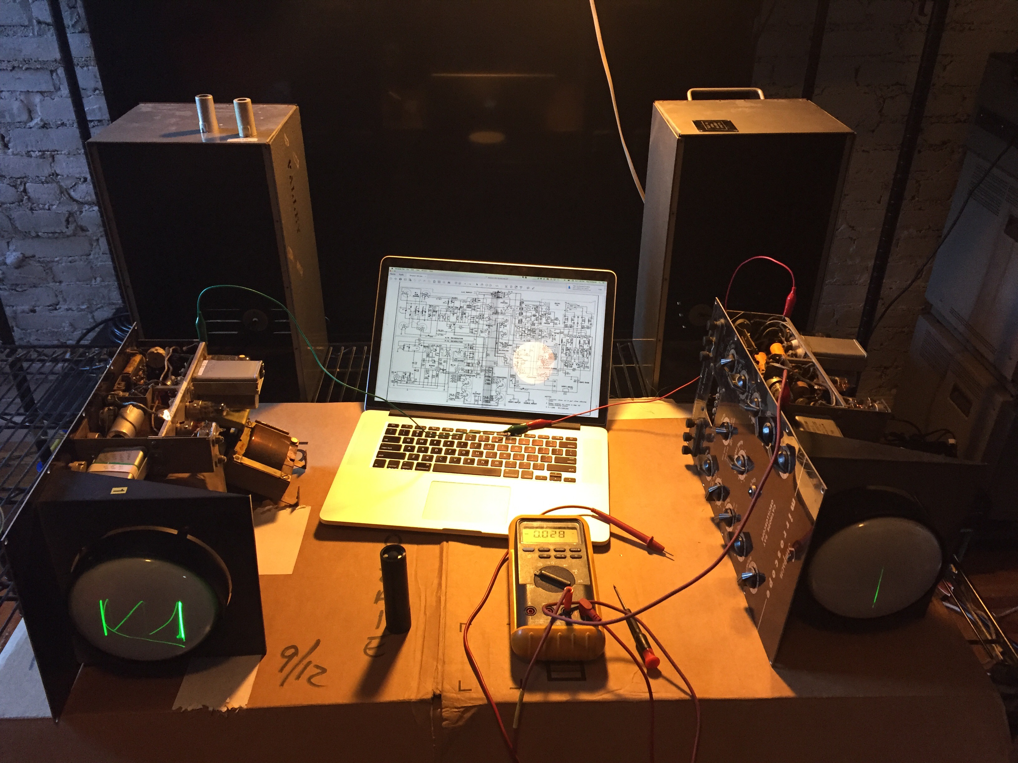
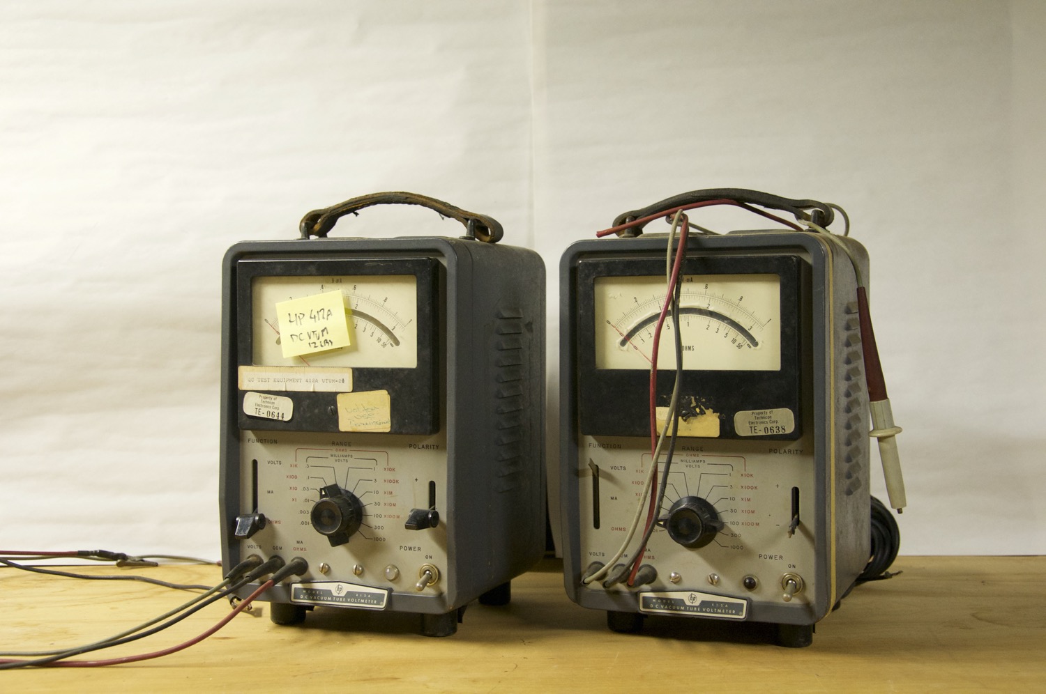
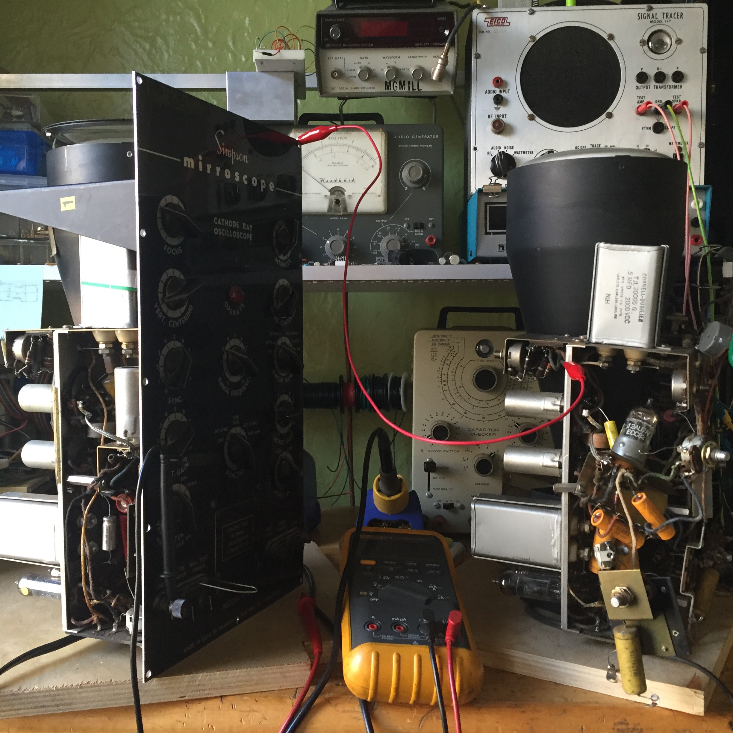
So I took Benton up on his offer of giving me the 2nd working scope, and it’s been super helpful in having a unit to compare to.  It’s hard to diagnose this thing without real schematics – the ones from the 480 are different enough to be more of a source of confusion.

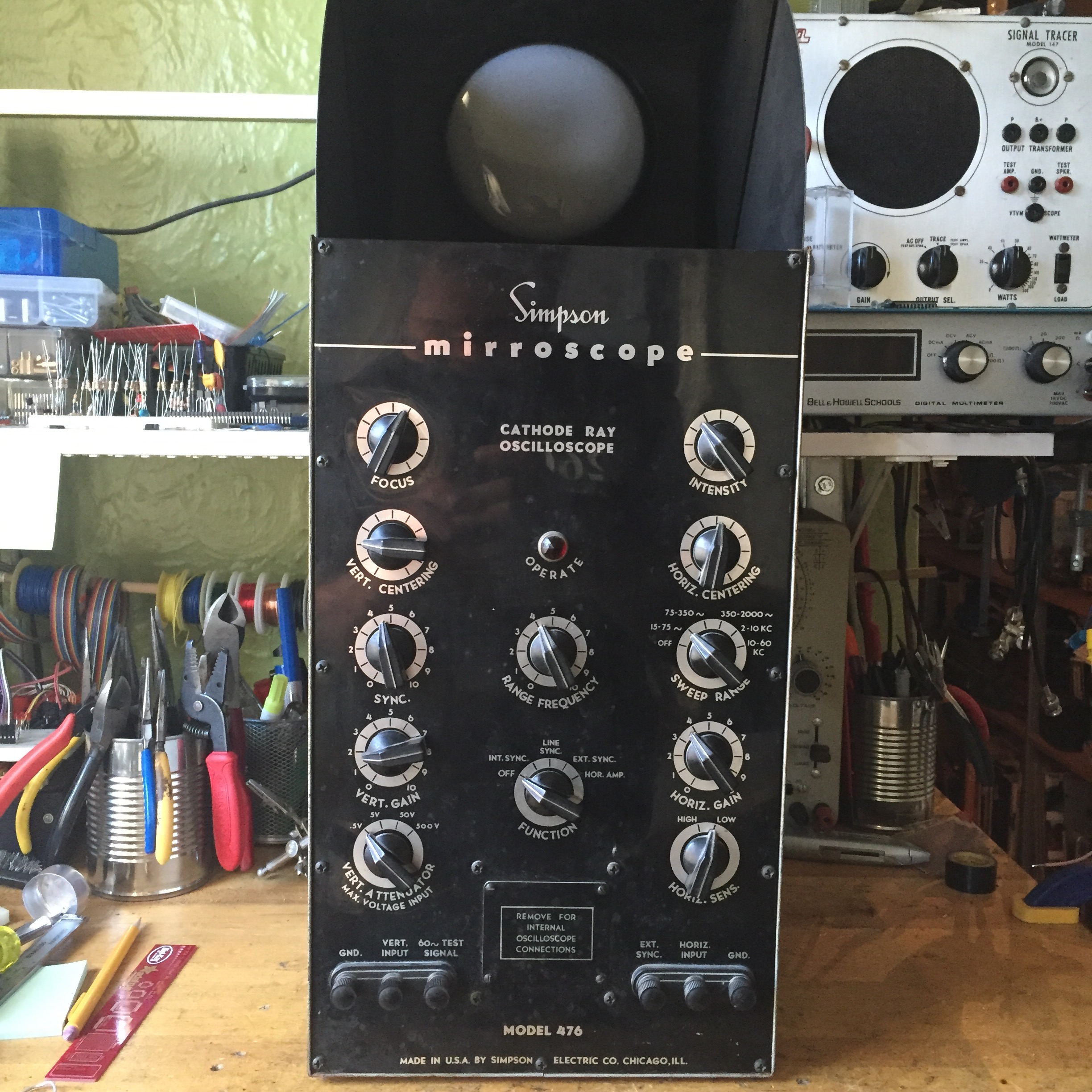
Before I got the second unit, I took the face place off in order to get better access to the components.  Unfortunately the face plate is what holds a lot of the unit together, so it’s in a very fragile state right now.  This thing was not made for easy service.  I have it on a plywood square that lets me move it around and spin it more easily.img_7016

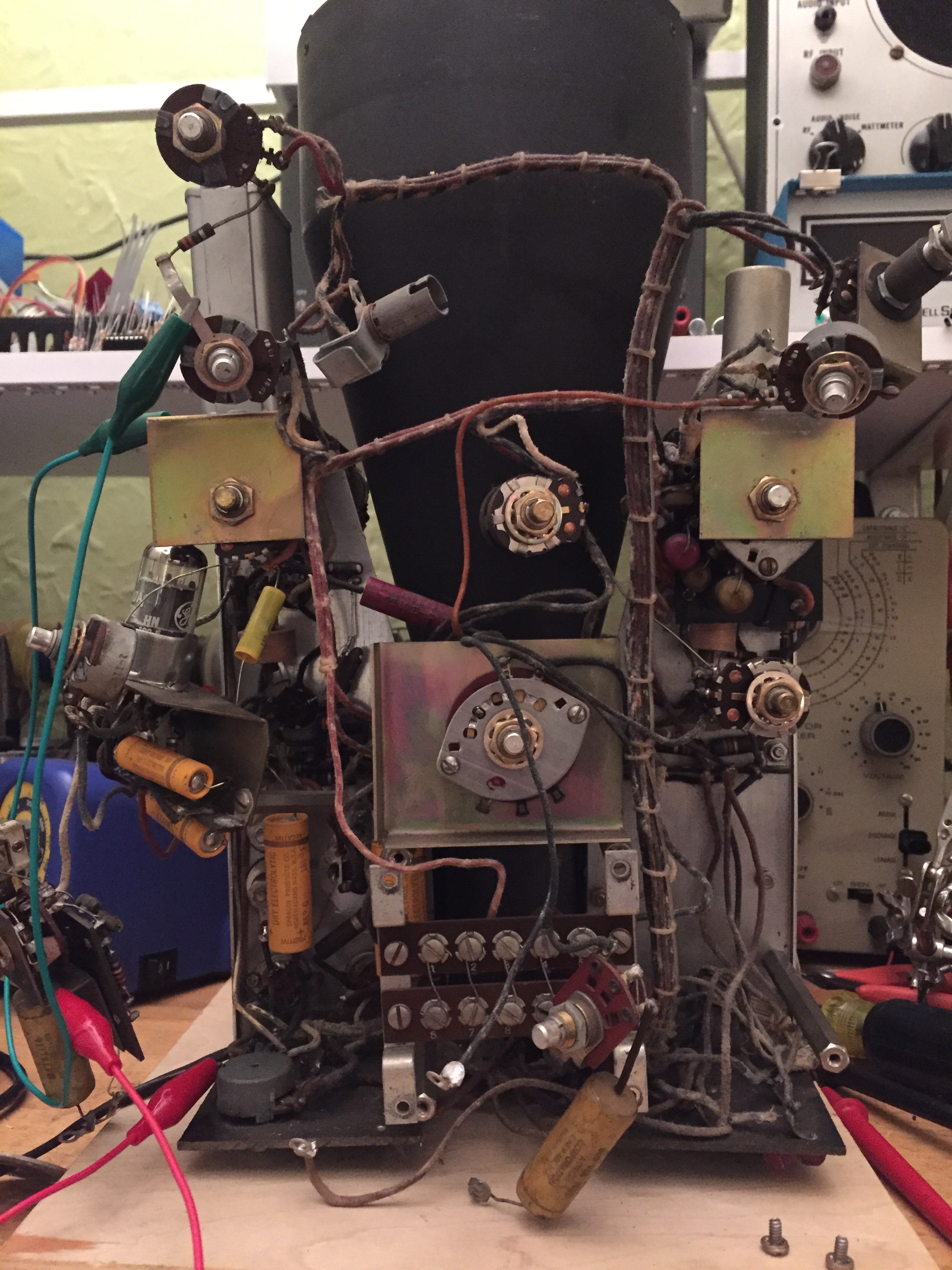
There’s some alligator clips to keep parts of the circuit grounded that were otherwise grounded through the face plate.

I also grabbed the FLIR One from the office and took some temperature measurements.  Here are the two hottest components:

A resistor in the vertical bias sectionimg_7007

A resistor in the power supply:
img_7003

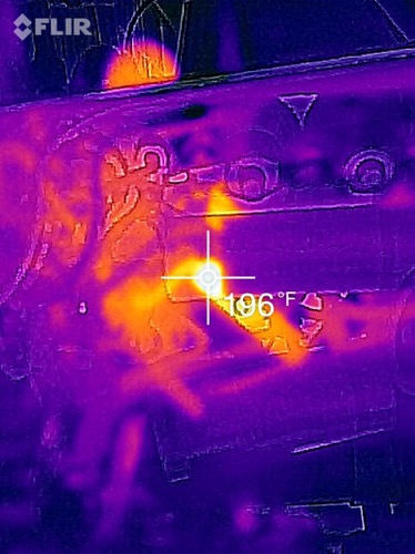
Both ALARMINGLY hot.  (pardon the mixed units, switched to Celsius 1/2 way through).  The FLIR is a really useful tool – the only issue is that at these close ranges, the visual and thermal layers don’t quite line up due to the physical spacing of the cameras.

I started checking values and taking measurements and noticed a few things:
screen-shot-2016-11-19-at-4-40-37-pm

Unlike in the 480, the 2nd section plate resistors are different between the horizontal and vertical sections.  Horizontal are the same 68k, while the vertical is 39k.  All have drifted high, and in some cases out of tolerance. These are 1W resistors, according to the manual.

R109, 2.7k 1/2W, that connects the cathode to ground, was open.  I replaced it with the closest thing I had, a 2.2k.  After that, I could make tiny adjustments in the vertical position, but the beam shape went to shit.

Shortly after that, Benton dropped off the second unit.  I removed it from it’s case, and started taking measurements.

img_7061

For starters, those resistors don’t get nearly as hot, so I started to get more confident that the problem was in the vertical biasing section (that bit with the pots hanging off the back)

Finally, I noticed the smoking gun:

img_7064-1

That piggybacked resistor pair?  That’s R98, called out as a 39k 1W in the schematic, but that there’s a 270Ω in parallel with a 330Ω, for a total of 150Ω !!.  But wait, It gets weirder.  That same resistor in the ‘working’ unit, is color coded as a 39k, but measures at 260k!  W.T.F!?.  When I place a closer value, 33k in the bad unit, I start to get a little more range, but the beam is still fuzzy.  When I replace it with the 260k resistor, I get tons of range, but still a fuzzy beam.

Meanwhile, on the horizontal side of the bad unit, that 39k resistor (R97) has been replaced with 3 50k in parallel, for 16k.

img_7066

Time to order a bunch of 1W resistors, I guess.


Simpson 476 Mirrorscope

Up next on the bench, a Simpson 476 Mirrorscope.

img_6849

This example belongs to Benton Bainbridge, an NYC video artist.  He’s got two, and this one needs the most help, so I figured I’d get it on my bench and get it working again.  That’s the hope, anyway.  As can be seen from the photo, the CRT points upward, and the operator views it through a 45° mirror, that flips up as the top of the chassis.  This yields a benchtop oscilloscope at an unheard of depth of only 8″.
It turns out, the manual for this beast is no where to be found.  I’ve reached out to Dave at Arktek manuals to see if he can dig up something.  I’ve gotten hard-to-find manuals from him before, so hopefully he can work some magic.  I also reached out to Steven Johnson, who’s got a great page and manuals for sale.  The Simpson 480 Genscope is approximately one of these mirrorscopes with a signal generator on either end.  I can’t even begin to imagine how unweildly that is to work on, but at least there’s a manual available.

I met Benton at his place, and we started comparing the “good one” and the “bad one”:

img_6824

Sweet DJ rig, yo

The problem seems to be in the vertical amplifier section, made up of (2) 6K6 twin triodes. One the good unit, the signal to the deflection plates varies between 170 – 240v while on the bad unit, they’re pegged at 350v, which appears to be full anode voltage.  Tubes were tested, and swapped, to no avail.  I brought my Heathkit TT-1, which Benton got a kick out of – it’s such a fun instrument to operate.

There were a few ground connections that appear to have been severed, but reconnecting them didn’t solve the issue.  There are a number of resistors that are running hotter, so much so that they’re discolored; however when measured cold, they appear to still be in tolerance.

There are a few differences between the 480 and the 476:

  • The 5Z4 rectifier is absent in the power supply.  This appears to power only the oscillators, so no surprise there.  The power supply consists of 2 6X4s, one for the CRT HV, at about 900v, and one for the rest of the circuits, at about 350v.
  • There’s an extra 12AU7 not present in the schematics for the 480.  I suspect this might be a pre-amp for the vertical input.  The 476 has more rages than the 480: 4 steps from .5v to 500v as opposed to ‘low / high’ on the 480.  Alternately, it’s a part of the sweep / trigger circuit?  I know that this is scope is capable of ‘synchronized’ operation, but I can’t for the life of me see how this thing triggers by looking at the schematic.
  • Some other component value differences.

Here’s the relevant part of the 480 schematic.  simpson-480

Benton offered that I should take both, to have  good one to compare with.  I declined, only wanting to bring two additional cubic feet of oscilloscope into my apartment, but I may take him up on it if I can’t get this figured out.  On old gear like this, I immediately suspect old caps in the power supply, but since the horizontal sections seems to be working (ish), that doesn’t screen out as the culprit.  I think I’ll just start checking / changing out caps in the PS for good measure, as I familiarize myself with this unit.

The other thing I’m definitely going to do is grab my boss’s FLIR One to scope out any really hot (or suspiciously cold) components.

But before I do anything else, I gotta order some more caps, my HV Electrolytic stock is almost depleted.  I kind of like running out of parts, it means I’m keeping busy.

Summer 2016 check-in

I’m just surfacing for a moment because I realize it’s been over 3 months without a post, which is just plain unacceptable.

HOPE XI just wrapped up, and I was there for at least a part of each of the three days – never really staying for the late stuff, but managed to catch at least 4 – 6 talks per day.  The highlight was (as it was two years ago) Deviant Ollan & Howard Payne’s tag-team talk.  This year was about the often abysmal state of physical security, manifested through commonly keyed locks.  Their last HOPE talk was on Elevator Hacking, and the subject of keys was one of it’s focal-points.  I highly recommend checking out the Elevator talk on YouTube.

Other highlights this year included:

I’ve started playing around with Collective Access – an open-source Collection Management System geared towards museums, libraries, and other archival institutions.  I found it after searching in vain for a WordPress solution for digitally curating the collection I present here.  I’ve got about a dozen objects added so far as I learn how it works and tailor it to my needs.  There is an underlying structure that makes it well suited for museum collections, but it’s highly configurable through the web interface;  Vocabulary, relationships, meta-data, object hierarchies, and user-interfaces can be customized without touching a line of code.
It’ll be a few more weeks until I’m comfortable enough with my schema, and I may start to post about my progress.

While at HOPE, I caught up with Evan of the Mid Atlantic Chapter of the Vintage Computer Federation, who (among other things) gave an interesting talk on his work researching early computers.  I’ve got the beginnings of an idea to use Collective Access to help them catalog their impressive inventory.  There are some real gems there, and beyond just cataloging, I’d love an opportunity to take some glamor shots.

The 514 is slowly coming to life – The +225v supply isn’t regulating to full voltage, and I’ve narrowed the problem down to something on the upper deck (the input, vertical amplifier, and calibrator).  With that disconnected, I get a nice, sharp, swept trace.

swept trace w/ upper deck disconnected

swept trace w/ upper deck disconnected

Sorry for the extended black-out, more to come!

Don’t desolider angry

desoldering DIPs with an iron, wick, and a sucker is about the most annoying thing a man can do with his precious time on this earth.  The frustration has probably chipped away days off my life, so there’s now a Hakko FR300 de-soldering iron on its way to me.

RIP DC508A, you never really had a chance.

On the plus side, there’s now one more working DC508A display available.

Canned air, your troubleshooting friend

After being on for about an hour, the intensity dropped to zero again.  After that I’d fire it up, and it would come on but quickly dim, and the intensity control wouldn’t effect the intensity, but move the beam slightly.

I traced the problem to the -15v supply, and finally the capacitor C143 (which I’d already replaced!).  I zeroed in on the problem by cooling areas using canned air with the bottle tilted to get a blast of frost.   The -15v supply would dip down to about 10v shortly after power up, but would rocket back up to -15v when I hit it with the frost, and I’d see the beam change.  A handy trick! With a fresh 10µF in it’s place, and it seems to be working for now.  I did need to hit the CRT bias trimpot to get the beam to extinguish with the intensity control fully counterclockwise.

TU-75B Wattmeter repair

As mentioned in my earlier post, the glass face had broken loose in the wattmeter on my TU-75B Variac.  I managed to re-attach the glass, learn a bit about this particular meter movement, and take a few nice shots while I had the unit apart.

First order of business was to clean out the gasketing material that originally held the glass in place.  It was black and brittle and not too terrible to scrape out of the inside of the meter body.  <sidenote> I do need to get a better understanding of what these original materials are – a table of common materials and finishes of the era, along with how to clean them and affix them would be a great resource to develop </sidenote>

IMG_4695.JPG

With the inside cleaned, the glass seated flush against the back of the opening.  I scratched up the inside wall a bit with the exacto knife, but it’s not visible when the meter is assembled.

IMG_4698.JPG

I picked up some Permatex 81730 glass sealant, which was recommended in this post about re-seating vacuum tube bases.  This video about re-seating CRT socket bases was where I first heard about it while researching how to reconnect the base on my OS-8/CU scope.  I figured I’d use it for this application as well, since it’s a similar plastic to glass connection (albeit without the heat of a CRT).  It was a little difficult to work with for this particular application; I wish it was a little more viscous and a little less sticky.  I also have some Permatex 80008 Form-a-Gasket sealant, which perhaps I’ll try next time.  The other gauge I have to re-face is going to be done with acrylic, so that that may be a different type of adhesive.  I was very conservative in applying the permatex, since it was easy to spread to visible parts of the glass and difficult to clean up while it was setting.

IMG_4704.JPG


With the glass face out of the way, I figured I’d get a few good macro shots of the innards.  The white bobbin on the top is a resistor, while I believe the brass stock in the back is a shunt.

DSC_0137


Here’s a closer look at the wire wound resistor.  DSC_0146

And the super fine wire from the V+ connection
DSC_0145

The way this meter is able to display wattage is by multiplying voltage by current.  It does this by way of nested coils:  one stationary and one on the movement.  Here is shown the meter at rest.
DSC_0143

here is the meter at half way, notice the inner bobbin is rotated.
DSC_0144


A few close-ups of the movement

DSC_0149

DSC_0151

DSC_0154


So then I re-installed the meter face and gave it a quick, damp wipe down.  Big Mistake.  See the streaks I’ve caused?  Sigh.. live and learn.  It was a stupid, ham-fisted move on my part.

DSC_0164

I also scratched up the glass a bit while I was removing the gasket from it’s face, but it’s not as noticeable  Here’s the finished product.  It seems to have a lot of momentum and/or friction to overcome, and as such doesn’t land on an accurate value when slowly incrementing the voltage.  I’ve only experimented with my 100w desk lamp, but it seems I can only get an accurate reading if I switch from off to full line voltage.  Alternately, it’s just out of cal (which seems odd, as there’s nothing to calibrate) and the over-swing just happens to land the needle on the right number.

DSC_0165

I took a picture with the meter against a ruler and some graph paper so I could recreate the next one.  Why I didn’t just trace it is beyond me.

IMG_4703.JPG

Continued adventures in nixie counting

Getting the Transistor Specialties 1519 back on the bench for some overdue continued exploration.

I’ve found that I can get the ‘B’ channel to increment it’s count by toggling the gate Start/Stop switch.  It’s a center return switch, and only by running the switch all the way from Stop to Start, across the center detent, can I get it to increment.

Some further discoveries:
this toggle trick only works around 110v line voltage.  I’m running it on a vairac, limiting it to 115v.
Earlier I think remarked that it was either 3 different flavors of boards, then I realized it might only be two?  It’s three.  The first counter card is different.  Though the layout is largely the same, some components are different, and it dawned on me only now that it’s probably because that card is the one’s counter, and thus needs to have a much higher bandwidth than those following it.  duh.

Here’s the beginnings of a schematic for the input card (one of two) ignore the ‘trigger level controls’ note.

TSI_1519_INPUT1